CYLINDER HEAD GASKET INSTALLATION
CAUTION / NOTICE / HINT
Note
-
Always be sure to check the tightening torque.
-
If the pressure lines are leaking after installation, they must be replaced.
-
Do not overtighten the pressure lines.
PROCEDURE
-
SELECT CYLINDER HEAD GASKET
-
Check the piston protrusions for each cylinder.
-
Clean the cylinder block with solvent.
-
Set the piston of the cylinder to be measured to slightly before TDC.
-
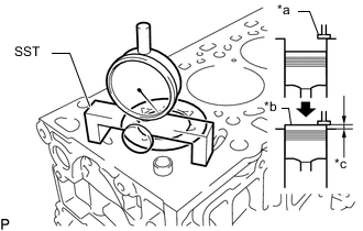
Text in Illustration *a Measuring Tip *b Measuring Point *c Protrusion Using SST, place a dial indicator on the cylinder block and set the measuring tip as shown in the illustration.
SST PZ4TB-04901-85 -
Set the dial indicator at 0 mm (0 in.).
Tech Tips
Make sure that the measuring tip is perpendicular to the cylinder head gasket surface and piston head when taking the measurements.
-
Find where the piston head protrudes most by slowly turning the crankshaft clockwise and counterclockwise.
-
Measure each cylinder at 2 places for a total of 8 measurements.
-
For the piston protrusion value of each cylinder, use the average of the 2 measurements of each cylinder.
Standard piston protrusion 0.420 to 0.680 mm (0.0165 to 0.0267 in.) If the protrusion is not as specified, remove the piston sub-assembly and connecting rod sub-assembly and reinstall them.
-
-
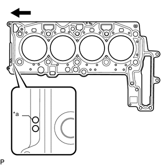
Text in Illustration *a Cylinder Head Gasket Hole 
Front Select a new cylinder head gasket.
New Installed Cylinder Head Gasket Thickness Cylinder Head Gasket Holes Specified Condition 1 Hole 0.95 mm (0.0374 in.) 2 Holes 1.05 mm (0.0413 in.) 3 Holes 1.15 mm (0.0452 in.) Tech Tips
Cylinder head gaskets have 1, 2, or 3 holes.
-
Select the largest piston protrusion value from the measurements and then select a new appropriate gasket according to the table below.
Cylinder Head Gasket Size Item Specified Condition Piston Protrusion 0.42 mm (0.0165 in.) or less 0.42 to 0.53 mm (0.0165 to 0.0208 in.) 0.53 to 0.68 mm (0.0208 to 0.0267 in.) Cylinder Head Gasket Holes 1 Hole 2 Holes 3 Holes
-
-
-
INSTALL CYLINDER HEAD GASKET
-
Place the cylinder head gasket in position on the cylinder block.
-
-
INSTALL CYLINDER HEAD SUB-ASSEMBLY
Note
-
Do not reuse the cylinder head bolts.
-
Make sure the ring pin shown in the illustration is not loose, deformed or otherwise damaged.
-
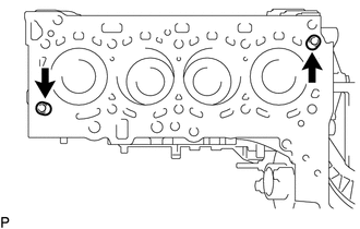
Place the cylinder head sub-assembly on the cylinder head gasket.
Note
Be careful of the installation direction.
-
Using an E10 "TORX" socket wrench, temporarily install the 5 bolts.
-
Apply a light coat of engine oil to under the heads of the new cylinder head bolts.
Note
Do not reuse the cylinder head bolts.
-
Temporarily install the new cylinder head bolts.
-
Step 1:
-
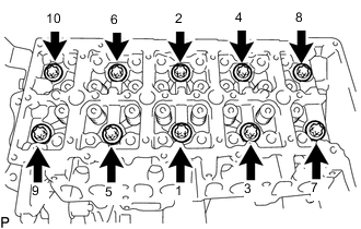
Using an E18 "TORX" socket wrench, uniformly tighten the 10 cylinder head bolts in several steps in the sequence shown in the illustration.
- Torque:
- 70 N*m { 714 kgf*cm, 52 ft.*lbf }
-
Mark the front of each cylinder head bolts head with paint.
-
Loosen the cylinder head bolts by 180° in the sequence shown in the illustration.
-
-
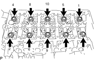
Step 2:
-
Tighten the 10 cylinder head bolts in several steps in the sequence shown in the illustration.
- Torque:
- 50 N*m { 510 kgf*cm, 37 ft.*lbf }
-
Retighten the cylinder head bolts by 120°.
-
-
Step 3:
-
Tighten the cylinder head bolts 120° further.
-
Check that the paint marks are now at a 240° angle to the RH.
-
-
Using an E10 "TORX" socket wrench, tighten the 5 bolts.
- Torque:
- 10 N*m { 102 kgf*cm, 7 ft.*lbf }
-
-
INSTALL GLOW PLUG ASSEMBLY
-
INSTALL ENGINE MOUNTING INSULATOR SUB-ASSEMBLY RH
-
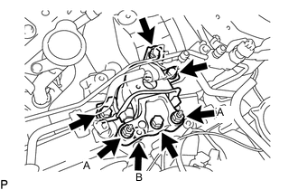
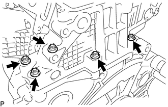
Install the engine mounting insulator sub-assembly RH with the 4 bolts and 3 nuts.
- Torque:
- for bolt and nut A
- 95 N*m { 969 kgf*cm, 70 ft.*lbf }
- for nut B
- 52 N*m { 530 kgf*cm, 38 ft.*lbf }
-
Attach the clamp to connect the air conditioner tube and accessory assembly.
-
Attach the 2 clamps to connect the suction pipe sub-assembly.
-
Remove the jack.
-
-
CONNECT RADIATOR RESERVOIR ASSEMBLY
-
Connect the radiator reservoir assembly with the 2 bolts.
- Torque:
- 5.0 N*m { 51 kgf*cm, 44 in.*lbf }
-
-
INSTALL NO. 2 TURBO INSULATOR
-
INSTALL EGR VALVE BRACKET
-
INSTALL EXHAUST MANIFOLD
-
INSTALL CAMSHAFT AND NO. 2 CAMSHAFT
-
CONNECT CABLE TO NEGATIVE BATTERY TERMINAL
Note
When disconnecting the cable, some systems need to be initialized after the cable is reconnected Click here.