CAMSHAFT INSTALLATION
CAUTION / NOTICE / HINT
Note
-
Always be sure to check the tightening torque.
-
If the pressure lines are leaking after installation, they must be replaced.
-
Do not overtighten the pressure lines.
PROCEDURE
-
INSPECT VALVE LASH ADJUSTER ASSEMBLY
-
INSTALL VALVE LASH ADJUSTER ASSEMBLY
-
Install the 16 valve lash adjuster assemblies to the cylinder head sub-assembly.
Note
Install the valve lash adjuster assemblies to their original positions.
-
-
INSTALL NO. 1 VALVE ROCKER ARM SUB-ASSEMBLY
-
Install the 16 No. 1 valve rocker arm sub-assemblies.
-
-
INSTALL CAMSHAFT HOUSING SUB-ASSEMBLY
-
Install 4 new gaskets.
-
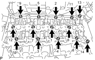
Uniformly tighten the 14 bolts in several steps in the sequence shown in the illustration.
-
Using an E10 "TORX" socket wrench, install camshaft housing sub-assembly with the 14 bolts.
- Torque:
- 13 N*m { 133 kgf*cm, 10 ft.*lbf }
-
-
SET NO. 1 CYLINDER TO TDC/COMPRESSION
-
INSTALL CAMSHAFT AND NO. 2 CAMSHAFT
-
Apply clean engine oil to the cam lobe of each camshaft, journals of the camshaft housing sub-assembly and No. 1 valve rocker arm sub-assemblies.
-
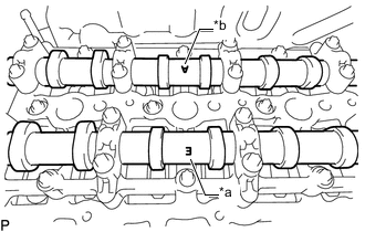
Place the camshaft and No. 2 camshaft on the camshaft housing sub-assembly as shown in the illustration so that mark E and mark A face upward.
Text in Illustration *a Mark E (Intake Side) *b Mark A (Exhaust Side) Note
Before and after setting the camshaft and No. 2 camshaft on the camshaft housing sub-assembly, check that the No. 1 valve rocker arm sub-assembly is firmly set to the valve lash adjuster assembly.
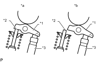
Text in Illustration *1 No. 1 Valve Rocker Arm Sub-assembly *2 Valve Stem *3 Valve Lash Adjuster Assembly *a CORRECT *b INCORRECT -
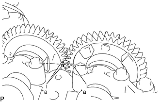
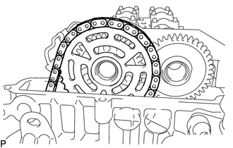
Text in Illustration *a Timing Mark Align the camshaft and No. 2 camshaft timing marks.
-
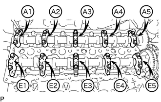
Set the 5 intake camshaft bearing caps and 5 exhaust camshaft bearing caps on the camshaft and No. 2 camshaft as shown in the illustration.
-
Using an E8 "TORX" socket wrench, partially tighten the 20 bolts.
-
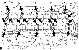
Uniformly tighten the 20 bolts in several steps in the sequence shown in the illustration.
- Torque:
- 10 N*m { 102 kgf*cm, 7 ft.*lbf }
-
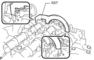
Text in Illustration *a No clearance Using SST, hold the camshaft and No. 2 camshaft.
SST PZ4TB-04961-12 Note
Make sure there is no clearance between SST and the camshaft housing sub-assembly.
-
Using an E10 "TORX" socket wrench, temporarily install the camshaft timing sprocket with No. 2 chain sub-assembly to the camshaft with the 3 bolts.
-
Step 1:
Tighten the 3 bolts.
- Torque:
- 10 N*m { 102 kgf*cm, 7 ft.*lbf }
-
Step 2:
Loosen the 3 bolts 90°.
-
-
Using a T45 "TORX" socket wrench, install the No. 2 timing chain guide with the bolt.
- Torque:
- 20 N*m { 204 kgf*cm, 15 ft.*lbf }
-
Using a 24 mm socket wrench, install the No. 2 chain tensioner assembly.
- Torque:
- 70 N*m { 714 kgf*cm, 52 ft.*lbf }
-
Using an E10 "TORX" socket wrench, install the camshaft timing sprocket with the 3 bolts.
- Torque:
- 14 N*m { 143 kgf*cm, 10 ft.*lbf }
-
Remove SST from the camshaft.
-
-
INSTALL NO. 2 ENGINE HANGER
-
INSTALL NO. 1 EXHAUST MANIFOLD HEAT INSULATOR
-
INSTALL NO. 1 TURBO INSULATOR
-
INSTALL CYLINDER HEAD COVER SUB-ASSEMBLY
-
Install 5 new gaskets to the cylinder head cover sub-assembly.
-
Install the cylinder head cover sub-assembly and tighten the 17 bolts.
Tech Tips
Refer to "SPECIFICATIONS - STANDARD BOLT" for the tightening torque.
-
-
INSTALL OIL FILLER CAP SUB-ASSEMBLY
-
INSTALL VACUUM CONTROL VALVE BRACKET
-
INSTALL INJECTOR ASSEMBLY
-
INSTALL NOZZLE LEAKAGE PIPE ASSEMBLY
-
INSTALL CAMSHAFT POSITION SENSOR
-
INSTALL COMMON RAIL ASSEMBLY
-
INSTALL INJECTION PIPE SUB-ASSEMBLY
-
INSTALL NO. 3 INJECTION PIPE SUB-ASSEMBLY
-
INSTALL INTAKE MANIFOLD
-
INSTALL NO. 1 VACUUM PIPE
-
CONNECT NO. 2 VACUUM HOSE ASSEMBLY
-
INSTALL ENGINE OIL LEVEL DIPSTICK GUIDE
-
CONNECT ENGINE WIRE
-
INSTALL AIR CLEANER CASE SUB-ASSEMBLY
-
INSTALL AIR CLEANER FILTER ELEMENT SUB-ASSEMBLY
-
INSTALL AIR CLEANER CAP SUB-ASSEMBLY WITH AIR CLEANER HOSE ASSEMBLY
-
INSTALL ENGINE COVER
-
INSTALL DIESEL THROTTLE BODY ASSEMBLY
-
INSTALL RADIATOR ASSEMBLY
-
CONNECT CABLE TO NEGATIVE BATTERY TERMINAL
Note
When disconnecting the cable, some systems need to be initialized after the cable is reconnected Click here.
-
INSPECT FOR FUEL LEAK
-
INSPECT FOR OIL LEAK