RELAY ON-VEHICLE INSPECTION
PROCEDURE
-
INSPECT INTEGRATION RELAY (EFI MAIN)
-
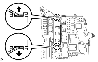
Using a screwdriver, detach the 2 claws, and then disconnect the 3 connectors to remove the integration relay from the engine room junction block.
Tech Tips
Tape the screwdriver tip before use.
-
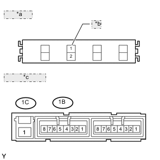
*a Fuse Side: *b EFI MAIN *c Connector Side: Check the EFI MAIN fuse.
-
Measure the resistance according to the value(s) in the table below.
Standard Resistance Tester Connection Condition Specified Condition EFI MAIN fuse Always Below 1 Ω If the result is not as specified, replace the EFI MAIN fuse.
-
-
Check the EFI MAIN relay.
-
Measure the resistance according to the value(s) in the table below.
Standard Resistance Tester Connection Condition Specified Condition 1C-1 - 1B-4 Battery voltage not applied to terminals 1B-2 and 1B-3 10 kΩ or higher 1B-1 - 1B-4 1C-1 - 1B-4 Battery voltage applied to terminals 1B-2 and 1B-3 Below 1 Ω 1B-1 - 1B-4 If the result is not as specified, replace the integration relay.
-
-
Install the integration relay.
-
-
INSPECT INTEGRATION RELAY (IGT/INJ)
-
Check the IGT/INJ fuse.
-
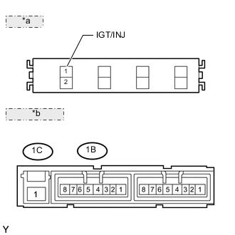
*a Fuse Side *b Connector Side Measure the resistance according to the value(s) in the table below.
Standard Resistance Tester Connection Condition Specified Condition IGT/INJ fuse Always Below 1 Ω If the result is not as specified, replace the IGT/INJ fuse.
-
-
Check the IGT/INJ relay.
-
Measure the resistance according to the value(s) in the table below.
Standard Resistance Tester Connection Condition Specified Condition 1C-1 - 1B-8 Battery voltage not applied to terminals 1B-6 and 1B-7 10 kΩ or higher 1B-1 - 1B-8 1C-1 - 1B-8 Battery voltage applied to terminals 1B-6 and 1B-7 Below 1 Ω 1B-1 - 1B-8 If the result is not as specified, replace the integration relay.
-
-
-
INSPECT NO. 1 IGNITION RELAY (IG1)
Note
The circuit opening relay is built into the main body ECU (instrument panel junction block).
-
Remove the main body ECU (instrument panel junction block).
-
Measure the resistance according to the value(s) in the table below.
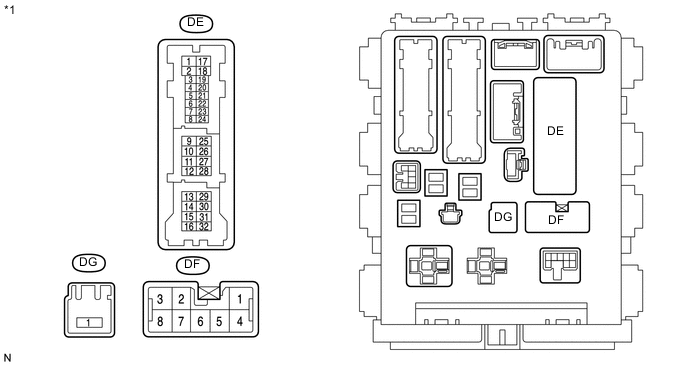
Text in Illustration *1 Component without harness connected
(Main body ECU)
Standard Resistance Tester Connection Condition Specified Condition DF-8 - DG-1 Battery voltage not applied to DF-3 (+) and DE-28 (-) 10 kΩ or higher DF-8 - DG-1 Battery voltage applied to DF-3 (+) and DE-28 (-) 150 Ω to 200 Ω If the result is not as specified, replace the main body ECU (instrument panel junction block).
-
Install the main body ECU (instrument panel junction block).
-
-
INSPECT NO. 2 IGNITION RELAY (IG2)
-
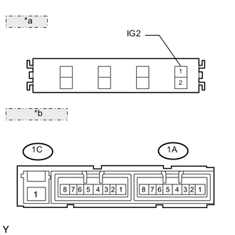
*a Fuse Side: *b Connector Side: Check the IG2 fuse.
-
Measure the resistance according to the value(s) in the table below.
Standard Resistance Tester Connection Condition Specified Condition IG2 fuse Always Below 1 Ω If the result is not as specified, replace the IG2 fuse.
-
-
Check the IG2 relay.
-
Measure the resistance according to the value(s) in the table below.
Standard Resistance Tester Connection Condition Specified Condition 1C-1 - 1A-4 Battery voltage not applied to terminals 1A-2 and 1A-3 10 kΩ or higher 1A-1 - 1A-4 1C-1 - 1A-4 Battery voltage applied to terminals 1A-2 and 1A-3 Below 1 Ω 1A-1 - 1A-4 If the result is not as specified, replace the integration relay.
-
-
-
INSPECT CIRCUIT OPENING RELAY (C/OPN)
Note
The circuit opening relay is built into the main body ECU (instrument panel junction block).
-
Measure the resistance according to the value(s) in the table below.
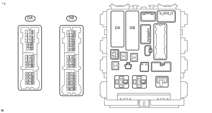
Text in Illustration *1 Component without harness connected
(Main body ECU)
Standard Resistance Tester Connection Condition Specified Condition DA-8 - DB-11 Battery voltage not applied to terminals DB-10 and DB-27 10 kΩ or higher DA-8 - DB-11 Battery voltage applied to terminals DB-10 and DB-27 Below 1 Ω If the result is not as specified, replace the main body ECU.
-