ECD SYSTEM(for Swirl Control Valve), Diagnostic DTC:P0102, P0103
| DTC Code | DTC Name |
|---|---|
| P0102 | Mass or Volume Air Flow Sensor "A" Circuit Low |
| P0103 | Mass or Volume Air Flow Sensor "A" Circuit High |
DESCRIPTION
The hot film air mass meter is attached to the air intake hose to the intake silencer.
The hot film air mass meter is a combined sensor. The hot film air mass meter detects the actual amount of air independently from the air pressure. In conjunction with other sensors, the ECM calculates the amount of fuel to be injected. An intake air temperature sensor is integrated into the hot film air mass meter. This sensor measures the temperature of the intake air before the exhaust turbocharger.
The flow path employed in the hot film air mass meter is divided into two paths. Centrifugal force separates the clean air from moisture and particulates. In one flow path the clean air destined for measurement is conducted to the monitoring element. The other flow path discharges moisture and particulates.
| DTC No. | DTC Detection Condition | Trouble Area |
|---|---|---|
| P0102 | Generated pulse period is 71 μsec. or less (MAF value is extremely high). (3 trip detection logic) |
|
| DTC No. | DTC Detection Condition | Trouble Area |
|---|---|---|
| P0103 | Generated pulse period is 833 μsec. or more (MAF value is extremely low). (3 trip detection logic) |
|
| DTC No. | Data List |
|---|---|
| P0102 P0103 |
MAF |
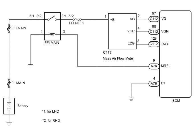
WIRING DIAGRAM
CAUTION / NOTICE / HINT
Note
-
When replacing the ECM, the ECM needs Registration and Initialization Click here.
-
After replacing the mass air flow meter, the ECM needs initialization Click here.
-
Inspect the fuses for circuits related to this system before performing the following inspection procedure.
Tech Tips
-
When the ECM must be replaced, before replacing the ECM, perform the "Learning Values Save" function using the GTS. Then after installing the new ECM, perform all of the initialization/registrations for the "Learning Values Write" function by following the instructions shown on the GTS display.
-
Read freeze frame data using the GTS. Freeze frame data records the engine condition when malfunctions are detected. When troubleshooting, freeze frame data can help determine if the vehicle was moving or stationary, if the engine was warmed up or not, and other data from the time the malfunction occurred.
PROCEDURE
-
CHECK HARNESS AND CONNECTOR (POWER SOURCE)
-
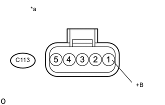
Text in Illustration *a Front view of wire harness connector
(to mass air flow meter)
Disconnect the mass air flow meter connector.
-
Measure the voltage according to the value(s) in the table below.
Standard Voltage Tester Connection Switch Condition Specified Condition C113-1 (+B) - Body ground Ignition switch ON 11 to 14 V
NG 
CHECK HARNESS AND CONNECTOR (MASS AIR FLOW METER - EFI MAIN RELAY) Click here
OK 
-
-
CHECK HARNESS AND CONNECTOR (MASS AIR FLOW METER - ECM)
-
Disconnect the mass air flow meter connector.
-
Disconnect the ECM connector.
-
Measure the resistance according to the value(s) in the table below.
Standard Resistance Tester Connection Condition Specified Condition C113-5 (VG) - C112-97 (VG) Always Below 1 Ω C113-4 (VGR) - C112-98 (VGR) Always Below 1 Ω C113-2 (E2G) - C112-129 (EVG) Always Below 1 Ω C113-5 (VG) or C112-97 (VG) - Body ground Always 10 kΩ or higher C113-4 (VGR) or C112-98 (VGR) - Body ground Always 10 kΩ or higher C113-2 (E2G) or C112-129 (EVG) - Body ground Always 10 kΩ or higher
OK
REPLACE MASS AIR FLOW METER Click here
NG
REPAIR OR REPLACE HARNESS OR CONNECTOR Click here
-
-
CHECK HARNESS AND CONNECTOR (MASS AIR FLOW METER - EFI MAIN RELAY)
-
Disconnect the mass air flow meter connector.
-
Remove the EFI MAIN relay from the engine room No. 1 relay block.
-
Measure the resistance according to the value(s) in the table below.
Standard Resistance (for LHD) Tester Connection Condition Specified Condition C113-1 (+B) - 3 (EFI MAIN relay holder) Always Below 1 Ω C113-1 (+B) or 3 (EFI MAIN relay holder) - Body ground Always 10 Ω or higher Standard Resistance (for RHD) Tester Connection Condition Specified Condition C113-1 (+B) - 5 (EFI MAIN relay holder) Always Below 1 Ω C113-1 (+B) or 5 (EFI MAIN relay holder) - Body ground Always 10 Ω or higher
OK
CHECK ECM POWER SOURCE CIRCUIT Click here
NG
-
-
REPAIR OR REPLACE HARNESS OR CONNECTOR
-
Repair or replace the harness or connector.
NEXT
CONFIRM WHETHER MALFUNCTION HAS BEEN SUCCESSFULLY REPAIRED Click here
-
-
CHECK ECM POWER SOURCE CIRCUIT
-
Check the ECM power source circuit Click here.
NEXT
CONFIRM WHETHER MALFUNCTION HAS BEEN SUCCESSFULLY REPAIRED Click here
-
-
REPLACE MASS AIR FLOW METER
-
Replace the mass air flow meter Click here.
-
Perform the air flow meter learning value reset Click here.
NEXT
-
-
CHECK WHETHER DTC OUTPUT RECURS (DTC P0102 AND/OR P0103)
-
Connect the GTS to the DLC3.
-
Turn the ignition switch to ON and turn the GTS on.
-
Clear the DTCs Click here.
-
Turn the ignition switch off and wait for 60 seconds or more [A].
-
Perform road test [B].
-
Repeat [A] and [B] for the number of trips detected.
-
Enter the following menus: Powertrain / Engine and ECT / Trouble Codes.
-
Read the DTCs.
Result Result Proceed to DTC P0102 and/or P0103 A No DTC output B
B 
END
A
-
-
REPLACE ECM
-
Replace the ECM Click here.
NEXT
-
-
CONFIRM WHETHER MALFUNCTION HAS BEEN SUCCESSFULLY REPAIRED
-
Connect the GTS to the DLC3.
-
Turn the ignition switch to ON and turn the GTS on.
-
Clear the DTCs Click here.
-
Turn the ignition switch off and wait for 60 seconds or more [A].
-
Perform road test [B].
-
Repeat [A] and [B] for the number of trips detected.
-
Enter the following menus: Powertrain / Engine and ECT / Trouble Codes.
-
Confirm that the DTC is not output again.
NEXT
END
-