STEERING KNUCKLE INSTALLATION
PROCEDURE
-
INSTALL STEERING KNUCKLE LH
-
Hold the front axle assembly in a vise between aluminum plates.
Note
When using a vise, do not overtighten it.
-
Install the front brake dust cover to the steering knuckle.
-
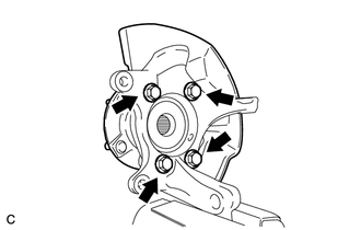
Install the front axle hub sub-assembly with the 4 bolts.
- Torque:
- 96 N*m { 979 kgf*cm, 71 ft.*lbf }
Note
Do not place the magnet rotor side of the hub and bearing so that it is facing downward, and do not allow the magnet rotor side to become damaged or contact foreign matter.
-
-
INSTALL FRONT LOWER BALL JOINT
-
Hold the front axle assembly in a vise between aluminum plates.
Note
When using a vise, do not overtighten it.
-
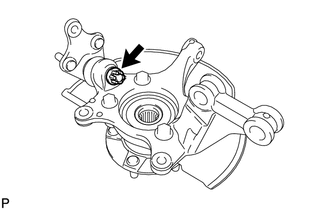
Install the front lower ball joint to the front axle assembly with the nut.
- Torque:
- 133 N*m { 1356 kgf*cm, 98 ft.*lbf }
-
Install a new cotter pin.
Note
If the holes for the cotter pin are not aligned, align the holes by tightening the nut as necessary up to an additional 60°.
-
-
INSTALL FRONT AXLE ASSEMBLY LH
-
CONNECT FRONT NO. 1 SUSPENSION LOWER ARM SUB-ASSEMBLY LH
-
CONNECT TIE ROD END SUB-ASSEMBLY LH
-
INSTALL FRONT DISC
-
INSTALL DISC BRAKE CYLINDER ASSEMBLY LH
-
INSTALL FRONT AXLE SHAFT NUT LH
-
REMOVE DISC BRAKE CYLINDER ASSEMBLY LH
-
REMOVE FRONT DISC
-
INSPECT FRONT AXLE HUB BEARING LOOSENESS
-
INSPECT FRONT AXLE HUB RUNOUT
-
INSTALL FRONT DISC
-
INSTALL DISC BRAKE CYLINDER ASSEMBLY LH
-
INSTALL FRONT FLEXIBLE HOSE
-
CONNECT FRONT SPEED SENSOR LH
-
STAKE FRONT AXLE SHAFT NUT LH
-
INSTALL FRONT WHEEL
- Torque:
- 103 N*m { 1050 kgf*cm, 76 ft.*lbf }
-
INSPECT AND ADJUST FRONT WHEEL ALIGNMENT
-
Inspect and adjust the front wheel alignment Click here.
-
-
CHECK SPEED SENSOR SIGNAL