MANUAL TRANSAXLE UNIT REASSEMBLY
PROCEDURE
-
INSTALL FRONT DIFFERENTIAL CASE FRONT TAPERED ROLLER BEARING
-
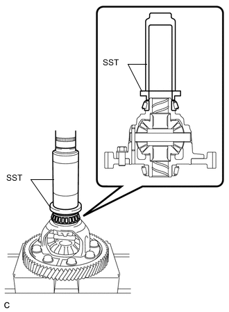
Using SST and a press, install a new front differential case front tapered roller bearing to the differential case.
- SST
- 09309-37010
- 09506-35010
-
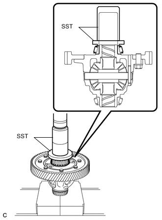
Using SST and a press, install the front differential case front tapered roller bearing (outer race) together with the front differential case front plate washer to the front transaxle case.
- SST
- 09950-60020 ( 09951-00680 )
- 09950-70010 ( 09951-07200 )
-
-
INSTALL FRONT DIFFERENTIAL CASE REAR TAPERED ROLLER BEARING
-
Using SST and a press, install a new front differential case rear tapered roller bearing to the differential case.
- SST
- 09636-20010
- 09726-40010
-
Using SST and a press, install the front differential case rear tapered roller bearing (outer race) together with the front differential case rear plate washer to the manual transmission case.
- SST
- 09309-36010
- 09950-60020 ( 09951-00730 )
- 09950-70010 ( 09951-07100 )
-
-
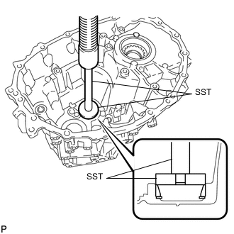
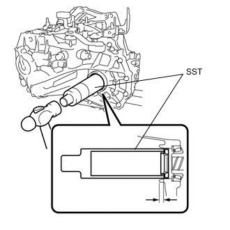
ADJUST DIFFERENTIAL SIDE BEARING PRELOAD
-
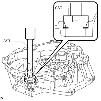
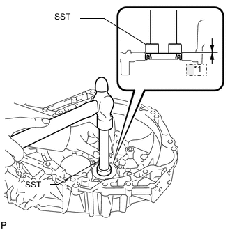
Coat the differential case assembly with gear oil and install it to the front transaxle case.
-
Install the manual transmission case with the 16 bolts.
- Torque:
- 29 N*m { 300 kgf*cm, 22 ft.*lbf }
-
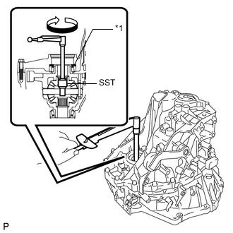
Text in Illustration *1 Plate Washer Using SST and a torque wrench, turn the differential case assembly clockwise and counterclockwise 2 or 3 times to allow the bearings to settle.
- SST
- 09564-32011
-
Using SST and a torque wrench, measure the preload.
- SST
- 09564-32011
Standard preload (at starting) New bearing 1.0 to 1.6 N*m (10 to 16 kgf*cm, 9 to 14 in.*lbf) Used bearing 0.8 to 1.3 N*m (8 to 13 kgf*cm, 7 to 11 in.*lbf) If the preload is not as specified, replace the front differential case rear plate washer with one of a different thickness. Use the table below to select a front differential case rear plate washer which will ensure that the preload is within the specification.
Standard Plate Washer Thickness Mark Specified Condition Mark Specified Condition 10 2.100 mm (0.0827 in.) 26 2.500 mm (0.0984 in.) 11 2.125 mm (0.0837 in.) 27 2.525 mm (0.0994 in.) 12 2.150 mm (0.0846 in.) 28 2.550 mm (0.100 in.) 13 2.175 mm (0.0856 in.) 29 2.575 mm (0.101 in.) 14 2.200 mm (0.0866 in.) 30 2.600 mm (0.102 in.) 15 2.225 mm (0.0876 in.) 31 2.625 mm (0.103 in.) 16 2.250 mm (0.0886 in.) 32 2.650 mm (0.104 in.) 17 2.275 mm (0.0896 in.) 33 2.675 mm (0.105 in.) 18 2.300 mm (0.0906 in.) 34 2.700 mm (0.106 in.) 19 2.325 mm (0.0915 in.) 35 2.725 mm (0.107 in.) 20 2.350 mm (0.0925 in.) 36 2.750 mm (0.108 in.) 21 2.375 mm (0.0935 in.) 37 2.775 mm (0.109 in.) 22 2.400 mm (0.0945 in.) 38 2.800 mm (0.110 in.) 23 2.425 mm (0.0955 in.) 39 2.825 mm (0.111 in.) 24 2.450 mm (0.0965 in.) 40 2.850 mm (0.112 in.) 25 2.475 mm (0.0974 in.) - - Tech Tips
-
Select a thicker plate washer to increase the preload, or a thinner plate washer to decrease the preload.
-
Make a memo as the torque values will be needed for the Adjust Output Shaft Bearing Preload procedure.
-
Remove the 16 bolts and manual transmission case.
-
Remove the differential case assembly from the front transaxle case.
-
Replace the installed front differential case rear plate washer with the one selected above.
-
-
INSTALL FRONT OUTPUT SHAFT BEARING
-
Install the output shaft cover to the front transaxle case.
Note
Insert the output shaft cover key into the case groove.
-
Using SST and a press, install the front output shaft bearing (outer race) to the front transaxle case.
- SST
- 09950-60010 ( 09951-00630 )
- 09950-70010
- 09950-70010
-
-
INSTALL REAR OUTPUT SHAFT BEARING
-
Using SST and a press, install the rear output shaft bearing (outer race) together with the rear output shaft bearing shim to the manual transmission case.
- SST
- 09950-60010 ( 09951-00590 )
- 09950-70010 ( 09951-07200 )
-
-
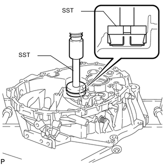
ADJUST OUTPUT SHAFT BEARING PRELOAD
-
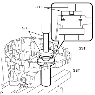
Coat the differential case assembly with gear oil and install it to the front transaxle case.
-
Coat the output shaft assembly with gear oil and install it to the front transaxle case.
-
Install the manual transmission case with the 16 bolts.
- Torque:
- 29 N*m { 300 kgf*cm, 22 ft.*lbf }
-
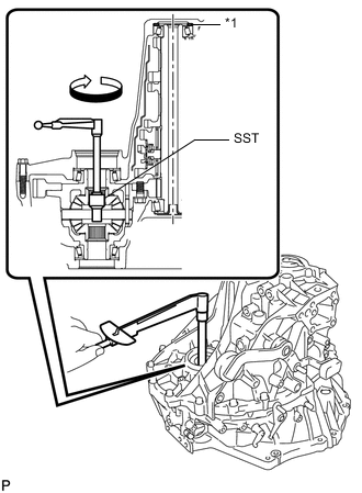
Text in Illustration *1 Bearing Shim Using SST and a torque wrench, turn the differential case assembly clockwise and counterclockwise 2 or 3 times to allow the bearings to settle.
- SST
- 09564-32011
-
Using SST and a torque wrench, measure the preload (value A). Calculate the rear output shaft bearing preload using the following formula.
- SST
- 09564-32011
Formula Value A - Differential side bearing preload = Output shaft bearing preload Standard preload (at starting) New bearing 4.6 to 7.9 N*m (47 to 80 kgf*cm, 41 to 69 in.*lbf) Used bearing 3.0 to 5.1 N*m (30 to 52 kgf*cm, 26 to 45 in.*lbf) If the preload is not as specified, replace the rear output shaft bearing shim with one of a different thickness. Use the table below to select a rear output shaft bearing shim which will ensure that the preload is within the specification.
Standard Bearing Shim Thickness Mark Specified Condition Mark Specified Condition 50 1.750 mm (0.0689 in.) 72 2.300 mm (0.0906 in.) 51 1.775 mm (0.0699 in.) 73 2.325 mm (0.0915 in.) 52 1.800 mm (0.0709 in.) 74 2.350 mm (0.0925 in.) 53 1.825 mm (0.0719 in.) 75 2.375 mm (0.0935 in.) 54 1.850 mm (0.0728 in.) 76 2.400 mm (0.0945 in.) 55 1.875 mm (0.0738 in.) 77 2.425 mm (0.0955 in.) 56 1.900 mm (0.0748 in.) 78 2.450 mm (0.0965 in.) 57 1.925 mm (0.0758 in.) 79 2.475 mm (0.0974 in.) 58 1.950 mm (0.0768 in.) 80 2.500 mm (0.0984 in.) 59 1.975 mm (0.0778 in.) 81 2.525 mm (0.0994 in.) 60 2.000 mm (0.0787 in.) 82 2.550 mm (0.100 in.) 61 2.025 mm (0.0797 in.) 83 2.575 mm (0.101 in.) 62 2.050 mm (0.0807 in.) 84 2.600 mm (0.102 in.) 63 2.075 mm (0.0817 in.) 85 2.625 mm (0.103 in.) 64 2.100 mm (0.0827 in.) 86 2.650 mm (0.104 in.) 65 2.125 mm (0.0837 in.) 87 2.675 mm (0.105 in.) 66 2.150 mm (0.0846 in.) 88 2.700 mm (0.106 in.) 67 2.175 mm (0.0856 in.) 89 2.725 mm (0.107 in.) 68 2.200 mm (0.0866 in.) 90 2.750 mm (0.108 in.) 69 2.225 mm (0.0876 in.) 91 2.775 mm (0.109 in.) 70 2.250 mm (0.0886 in.) 92 2.800 mm (0.110 in.) 71 2.275 mm (0.0896 in.) - - Tech Tips
Select a thicker bearing shim to increase the preload, or a thinner bearing shim to decrease the preload.
-
Remove the 16 bolts and manual transmission case.
-
Remove the output shaft assembly from the front transaxle case.
-
Remove the differential case assembly from the front transaxle case.
-
Replace the installed rear output shaft bearing shim with the one selected above.
-
-
INSTALL OUTER SHIFT LEVER OIL SEAL
-
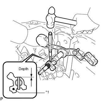
*1 Depth Using SST and a hammer, install a new outer shift lever oil seal to the manual transmission case.
- SST
- 09950-60010 ( 09951-00260 )
- 09950-70010 ( 09951-07100 )
Standard depth 0.5 to 1.0 mm (0.0197 to 0.0393 in.) -
Coat the lip of the outer shaft lever oil seal with MP grease.
-
-
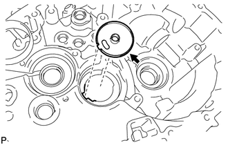
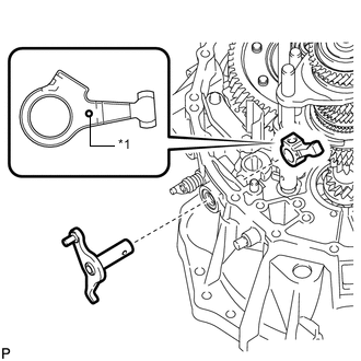
INSTALL OUTER NO. 1 SHIFT LEVER
-
Text in Illustration *1 Mark Install the inner No. 1 shift lever, outer shift lever spacer and outer No. 1 shift lever to the manual transmission case.
Tech Tips
Install the inner No. 1 shift lever with its mark facing outside of the manual transmission case.
-
Using a 5 mm pin punch and hammer, install the inner shift lever slotted spring pin to the inner No. 1 shift lever.
Standard depth -0.5 to 0.5 mm (-0.0197 to 0.0197 in.)
-
-
INSTALL MANUAL TRANSMISSION OIL SEPARATOR SUB-ASSEMBLY
-
Install the manual transmission oil separator sub-assembly to the manual transmission case with the 4 bolts.
- Torque:
- 17 N*m { 173 kgf*cm, 13 ft.*lbf }
Tech Tips
Make sure that the end tabs of the manual transmission oil separator sub-assembly are inserted in the grooves of the manual transmission case.
-
-
INSTALL TRANSMISSION OIL SEPARATOR
-
For manual transmission case side:
Install the transmission oil separator to the manual transmission case with the 2 bolts.
- Torque:
- 17 N*m { 173 kgf*cm, 13 ft.*lbf }
Tech Tips
Make sure that the tip of the transmission oil separator is inserted in the groove of the transmission case.
-
-
INSTALL NO. 1 OIL RECEIVER PIPE
-
Install the No. 1 oil receiver pipe to the manual transmission case.
Tech Tips
Make sure that the No. 1 oil receiver pipe fully contacts the manual transmission case.
-
-
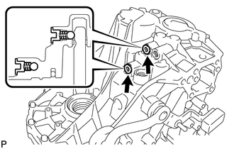
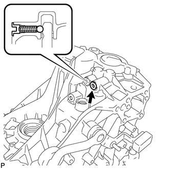
INSTALL STRAIGHT PIN
-
Text in Illustration *1 8.5 to 9.5 mm Using a plastic-faced hammer, tap in 5 new straight pins to the specified protrusion height.
Protrusion height 8.5 to 9.5 mm (0.335 to 0.374 in.)
-
-
INSTALL REVERSE RESTRICT PIN ASSEMBLY
-
Install the reverse restrict pin assembly to the front transaxle case.
-
-
INSTALL BREATHER PLUG
-
Using SST and a hammer, install the breather plug to the front transaxle case.
- SST
- 09350-30020 ( 09350-07110 )
-
-
INSTALL TRANSMISSION OIL SEPARATOR
-
For front transaxle case side:
Install the transmission oil separator to the front transaxle case with the 4 bolts.
- Torque:
- 17 N*m { 173 kgf*cm, 13 ft.*lbf }
-
-
INSTALL FRONT TRANSAXLE CASE OIL SEAL
-
*1 Depth Using SST and a hammer, install a new front transaxle case oil seal to the front transaxle case.
- SST
- 09950-60010 ( 09951-00350 )
- 09950-70010 ( 09951-07100 )
Standard depth 0.9 to 1.9 mm (0.0354 to 0.0748 in.) -
Coat the lip of the front transaxle case oil seal with MP grease.
-
-
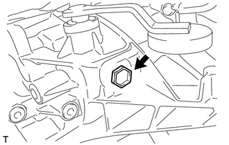
INSTALL TRANSMISSION MAGNET
-
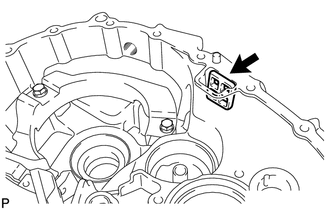
Clean the transmission magnet and install it to the front transaxle case.
-
-
INSTALL INPUT SHAFT COVER
-
Install the input shaft cover to the manual transmission case.
Note
Insert the input shaft cover key into the manual transmission case groove.
-
-
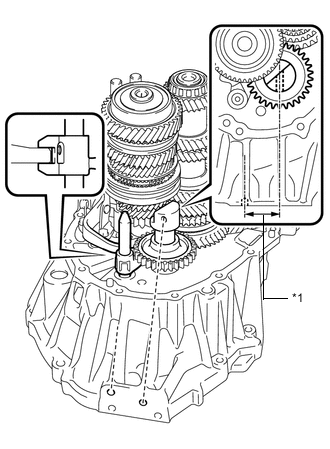
INSTALL REAR INPUT SHAFT BEARING SHIM
-
Install the rear input shaft bearing shim to the manual transmission case.
Note
Apply grease to the shim to prevent it from falling off of the case during assembly.
-
Measure the distance between the end of the manual transmission case and rear input shaft bearing shim (Dimension A).
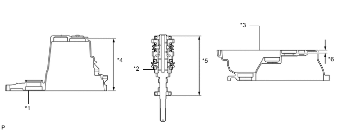
-
Measure the distance between the end of the front transaxle case and installation surface of the front input shaft bearing (Dimension B).
Text in Illustration *1 Manual Transmission Case *2 Input Shaft Assembly *3 Front Transaxle Case *4 Dimension A *5 Dimension C *6 Dimension B -
Measure the distance between both input shaft bearing outer races (Dimension C).
Note
Measure Dimension C with each bearing having no axial clearance.
-
Calculate the rear input shaft bearing shim clearance using the following formula.
Formula (Dimension A + Dimension B) - Dimension C - Rear input shaft bearing shim thickness = Between 0.02 mm (0.000788 in.) and 0.14 mm (0.00551 in.) If the clearance is not as specified, replace the rear input shaft bearing shim with one of a different thickness. Use the table below to select a rear input shaft bearing shim which will ensure that the clearance is within the specification.
Standard Rear Input Shaft Bearing Shim Thickness Mark Specified Condition 08 1.30 mm (0.0512 in.) 09 1.35 mm (0.0531 in.) 10 1.40 mm (0.0551 in.) 11 1.45 mm (0.0571 in.) 12 1.50 mm (0.0591 in.) 13 1.55 mm (0.0610 in.) 14 1.60 mm (0.0630 in.) 15 1.65 mm (0.0650 in.) 16 1.70 mm (0.0669 in.) 17 1.75 mm (0.0689 in.) 18 1.80 mm (0.0709 in.) 19 1.85 mm (0.0728 in.) -
Coat the selected rear input shaft bearing shim with MP grease, and then replace the installed rear input shaft bearing shim with the one selected above.
Note
Do not apply MP grease to the oil grooves.
-
-
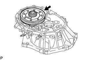
INSTALL DIFFERENTIAL CASE ASSEMBLY
-
Coat the differential case tapered roller bearing with gear oil and install it to the front transaxle case.
-
-
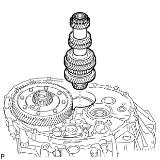
INSTALL INPUT SHAFT ASSEMBLY
-
Apply gear oil to all sliding and rotating parts.
-
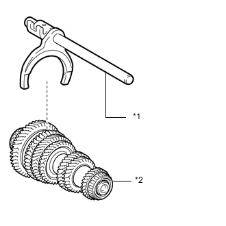
Text in Illustration *1 No. 1 Gear Shift Fork Shaft *2 Output Shaft Coat the No. 1 gear shift fork shaft with gear oil and install it.
-
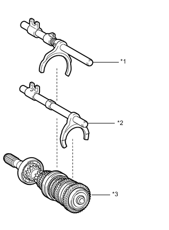
Text in Illustration *1 No. 2 Gear Shift Fork Shaft *2 No. 3 Gear Shift Fork Shaft *3 Input Shaft Coat the No. 2 gear shift fork shaft and No. 3 gear shift fork shaft with gear oil and install them.
-
Temporarily install the output shaft with No. 1 gear shift fork shaft to the input shaft assembly, and tie them with a rope or string.
-
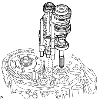
Install the input shaft assembly, output shaft assembly and 3 gear shift fork shaft assemblies to the front transaxle case.
-
-
INSTALL OUTER SELECT LEVER OIL SEAL
-
*1 Depth Using SST and a hammer, install a new outer select lever oil seal to the front transaxle case.
- SST
- 09950-60010 ( 09951-00240 )
- 09950-70010 ( 09951-07100 )
Standard depth 0.5 to 1.0 mm (0.0197 to 0.0393 in.) -
Coat the lip of the outer select lever oil seal with MP grease.
-
-
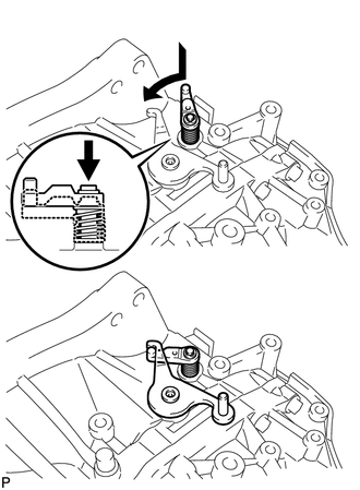
INSTALL OUTER SELECT LEVER
-
Text in Illustration *1 Mark Install the inner select lever and outer select lever to the front transaxle case.
Tech Tips
Install the inner select lever with its mark facing outside of the front transaxle case.
-
-
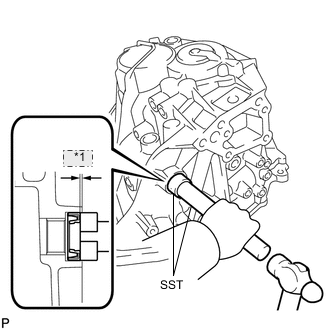
INSTALL SHIFT AND SELECT LEVER SHAFT ASSEMBLY
-
Install the shift interlock plate and shift and select lever shaft assembly to the front transaxle case, and then turn them counterclockwise.
Tech Tips
When installing the shift interlock plate, make sure to engage it with the inner select lever.
-
Coat the threads of the inner select lever set bolt with adhesive and install it using a 6 mm hexagon socket wrench.
Adhesive Toyota Genuine Adhesive 1344, Three Bond 1344 or equivalent - Torque:
- 28 N*m { 286 kgf*cm, 21 ft.*lbf }
-
-
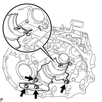
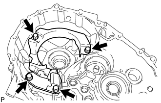
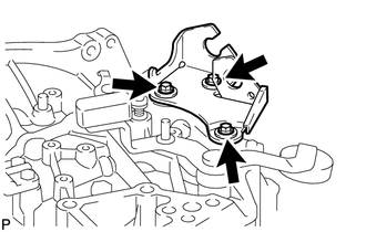
INSTALL REVERSE SHIFT ARM BRACKET ASSEMBLY
-
Install the reverse shift arm bracket assembly to the front transaxle case with the 2 bolts.
- Torque:
- 17 N*m { 173 kgf*cm, 13 ft.*lbf }
-
-
INSTALL REVERSE SHIFT FORK SHAFT ASSEMBLY
-
Coat the reverse shift fork shaft assembly with gear oil and install it to the front transaxle case.
-
-
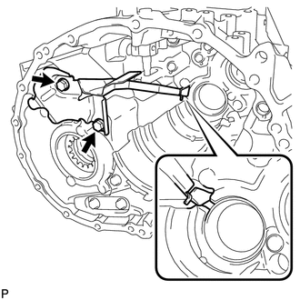
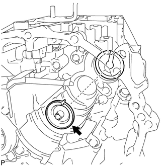
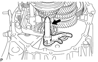
INSTALL REVERSE IDLER GEAR SUB-ASSEMBLY
-
Text in Illustration *1 Parallel Coat the reverse idler gear sub-assembly, thrust washer and reverse idler gear shaft with gear oil, and install them as shown in the illustration.
Tech Tips
Raise the edge of the reverse shift arm bracket assembly and connect the reverse shift arm bracket assembly to the reverse shift fork shaft assembly.
Note
Make sure that the axis of the reverse idler gear shaft bolt hole is parallel to the axle of the bolt hole of the front transaxle case, as shown in the illustration.
-
-
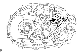
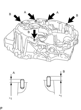
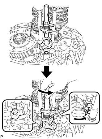
INSTALL MANUAL TRANSMISSION CASE
-
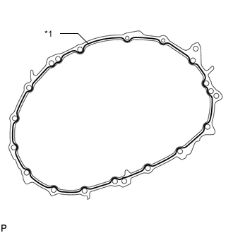
Apply seal packing to the manual transmission case as shown in the illustration.
Seal packing Toyota Genuine Seal Packing 1281, Three Bond 1281 or equivalent Standard seal diameter 1.2 mm (0.0472 in.) Text in Illustration *1 Seal Packing Note
-
Remove any oil from the contact surfaces.
-
Assemble the parts within 10 minutes of application. Otherwise, the packing (FIPG) material must be removed and reapplied.
-
-
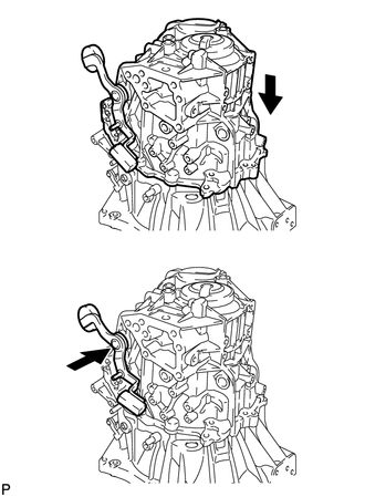
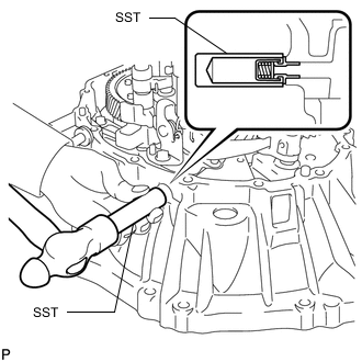
Push the outer No. 1 shift lever and install the manual transmission case.
Tech Tips
Pushing the outer No. 1 shift lever allows the manual transmission case to be installed.
-
Turn the outer No. 1 shift lever counterclockwise and then pull it.
-
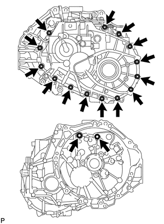
Install the 16 bolts to the manual transmission case.
- Torque:
- 29 N*m { 300 kgf*cm, 22 ft.*lbf }
-
-
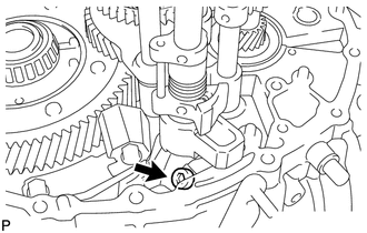
INSTALL OUTER SHIFT LEVER E RING
-
Install the E ring to the outer No. 1 shift lever.
-
-
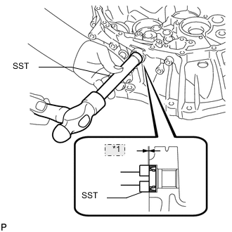
INSTALL FRONT TRANSAXLE CASE OIL SEAL
-
*1 Depth Using SST and a hammer, install a new transaxle case oil seal to the front transaxle case.
- SST
- 09630-24014 ( 09620-24051 )
- 09950-60010 ( 09951-00410, 09951-00530, 09952-06010 )
- 09950-70010 ( 09951-07100 )
Standard depth 1.4 to 2.4 mm (0.0552 to 0.0944 in.) Note
Do not damage the oil seal lip.
-
Coat the lip of the transaxle case oil seal with MP grease.
-
-
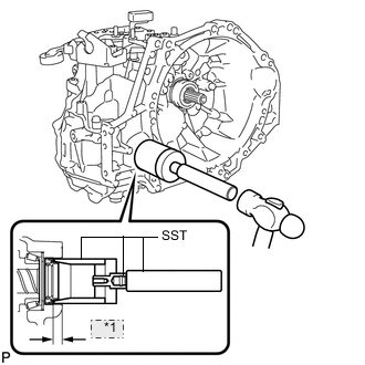
INSTALL TRANSMISSION CASE OIL SEAL
-
Using SST and a hammer, install a new transmission case oil seal to the manual transmission case.
- SST
- 09316-60011 ( 09316-00011 )
Standard depth 10.6 to 11.6 mm (0.417 to 0.456 in.) Note
Do not damage the oil seal lip.
-
Coat the lip of the transmission case oil seal with MP grease.
-
-
INSTALL SHIFT DETENT BALL
-
Install the 2 shift detent balls and 2 compression springs to the manual transmission case.
Note
Be careful not to drop the ball into the manual transmission case.
-
Coat the threads of the 2 shift detent ball plugs with adhesive and install them using a 6 mm hexagon socket wrench.
Adhesive Toyota Genuine Adhesive 1344, Three Bond 1344 or equivalent - Torque:
- 22 N*m { 224 kgf*cm, 16 ft.*lbf }
-
Install the shift detent ball and compression spring to the manual transmission case.
Note
Be careful not to drop the ball into the manual transmission case.
-
Coat the threads of the shift detent ball plug with adhesive and install it using a 6 mm hexagon socket wrench.
Adhesive Toyota Genuine Adhesive 1344, Three Bond 1344 or equivalent - Torque:
- 22 N*m { 224 kgf*cm, 16 ft.*lbf }
-
-
INSTALL LOCK BALL PIN
-
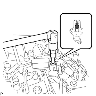
Install the lock ball pin and compression spring to the manual transmission case.
Note
Be careful not to drop the lock ball pin into the manual transmission case.
-
Coat the threads of the shift detent ball plug with adhesive and install it using a 10 mm hexagon socket wrench.
Adhesive Toyota Genuine Adhesive 1344, Three Bond 1344 or equivalent - Torque:
- 25 N*m { 250 kgf*cm, 18 ft.*lbf }
-
-
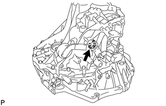
INSTALL REVERSE IDLER GEAR SHAFT BOLT
-
Install a new gasket and the reverse idler gear shaft bolt to the manual transmission case.
- Torque:
- 30 N*m { 306 kgf*cm, 22 ft.*lbf }
-
-
INSTALL NO. 1 LOCK BALL ASSEMBLY
-
Coat the threads of the No. 1 lock ball assembly with adhesive and install it to the manual transmission case.
Adhesive Toyota Genuine Adhesive 1344, Three Bond 1344 or equivalent - Torque:
- 29 N*m { 300 kgf*cm, 22 ft.*lbf }
-
-
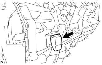
INSTALL TRANSMISSION CASE PLUG
-
Install a new gasket and the transmission case plug to the manual transmission case.
- Torque:
- 28 N*m { 286 kgf*cm, 21 ft.*lbf }
-
-
INSTALL NO. 1 CLUTCH HOUSING COVER
-
Install the No. 1 clutch housing cover to the front transaxle case.
-
-
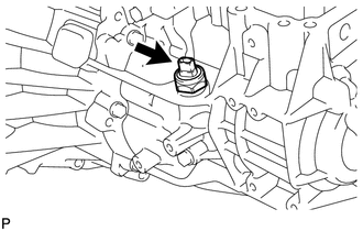
INSTALL RELEASE CYLINDER BLEEDER PLUG
-
Install the release cylinder bleeder plug to the clutch release bleeder sub-assembly.
- Torque:
- 8.4 N*m { 86 kgf*cm, 74 in.*lbf }
-
-
INSTALL RELEASE CYLINDER BLEEDER PLUG CAP
-
Install the release cylinder bleeder plug cap onto the release cylinder bleeder plug.
-
-
INSTALL CLUTCH RELEASE WITH BEARING CYLINDER ASSEMBLY
-
REMOVE CLUTCH RELEASE BLEEDER SUB-ASSEMBLY
-
INSPECT CLUTCH PIPE LINE
-
INSTALL CLUTCH RELEASE BLEEDER SUB-ASSEMBLY
-
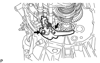
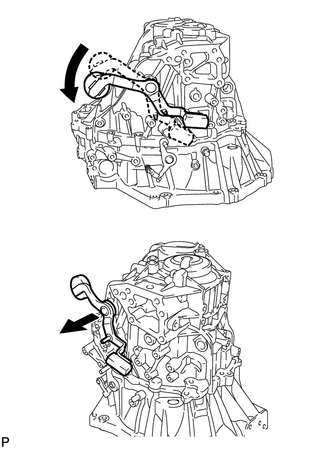
INSTALL CONTROL CABLE BRACKET ASSEMBLY
-
Hook the outer lever of the manual transaxle to the low fixture lever to secure it.
-
Install the control cable bracket assembly to the manual transmission case with the 3 bolts.
- Torque:
- 17 N*m { 173 kgf*cm, 13 ft.*lbf }
-
-
INSTALL MANUAL TRANSMISSION CASE PLUG
-
Install a new gasket and the manual transmission case plug to the manual transmission case.
- Torque:
- 40 N*m { 408 kgf*cm, 30 ft.*lbf }
-
-
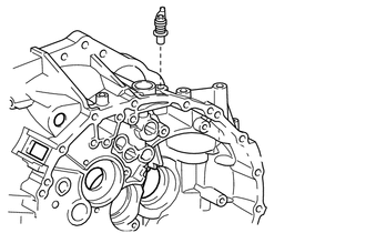
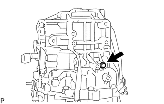
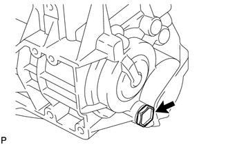
INSTALL BACK-UP LIGHT SWITCH ASSEMBLY
-
Using a 27 mm deep socket wrench, install a new gasket and the back-up light switch to the manual transmission case.
- Torque:
- 40 N*m { 408 kgf*cm, 30 ft.*lbf }
-
-
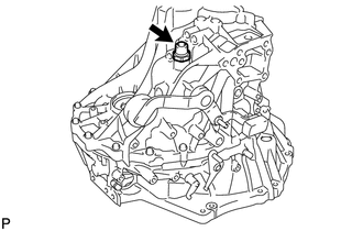
INSTALL MANUAL TRANSMISSION FILLER PLUG
-
Install a new gasket and the manual transmission filler plug to the manual transmission case.
- Torque:
- 39 N*m { 400 kgf*cm, 29 ft.*lbf }
-
-
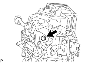
INSTALL MANUAL TRANSMISSION DRAIN PLUG
-
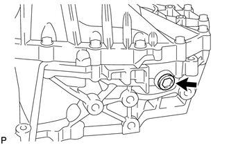
Using a 10 mm hexagon socket wrench, install a new gasket and the manual transmission drain plug to the front transaxle case.
- Torque:
- 45 N*m { 459 kgf*cm, 33 ft.*lbf }
-