TRANSMISSION CONTROL CABLE INSTALLATION
PROCEDURE
-
INSTALL TRANSMISSION CONTROL CABLE ASSEMBLY
-
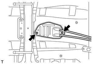
Attach the grommet of the control cable assembly with the 2 nuts.
- Torque:
- 5.0 N*m { 51 kgf*cm, 44 in.*lbf }
-
Attach the bracket of the control cable assembly with the bolt.
- Torque:
- 5.0 N*m { 51 kgf*cm, 44 in.*lbf }
-
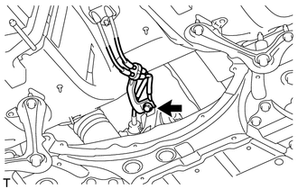
Connect the 2 cables to the control cable bracket with 2 new clips.
-
Connect the 2 cables to the transaxle and install the 2 clips.
-
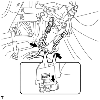
Engage the 2 claws, and install the control cable assembly to the shift lever assembly.
Note
Make sure that the claws are firmly engaged.
-
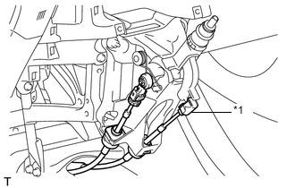
Text in Illustration *1 Select Cable Install the control shift cable to the shift lever assembly.
-
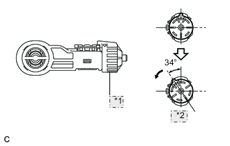
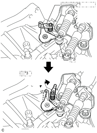
*1 Stopper *2 Turn Release the lock of the cable length adjustment structure of the select cable.
-
Turn the stopper.
-
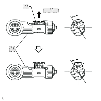
*1 Lock Piece *2 Pull out *3 Case Pull the lock piece outward from the case to release the lock.
-
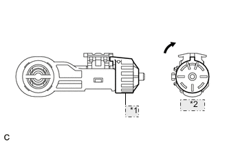
*1 Stopper *2 Return Return the stopper.
-
-
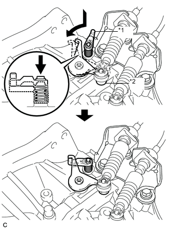
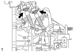
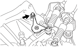
Text in Illustration *1 Reverse Restrict Pin Assembly *2 Outer Lever w/ Reverse Restrict Pin Assembly:
Hook the outer lever of the manual transaxle onto the reverse restrict pin assembly to secure it.
-
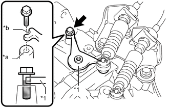
*1 Outer Lever *a Installation hole for transmission control select cable adjustment *b Cutout w/o Reverse Restrict Pin Assembly:
Align the outer lever cutout with the hole for adjusting the transmission control select cable, and insert the bolt by hand to secure the outer lever as shown in the illustration.
Note
In order to avoid case damage, do not push the bolt in forcefully.
Tech Tips
-
Use a bolt with a diameter of 6.0 mm (0.236 in.) and a length of at least 18 mm (0.709 in.) or more.
-
Depending on the actual bolt diameter, it may be difficult to insert the bolt. In that case, as there is some variation in actual bolt diameters, use a 6.0 mm (0.236 in.) bolt with a comparatively small diameter.
-
-
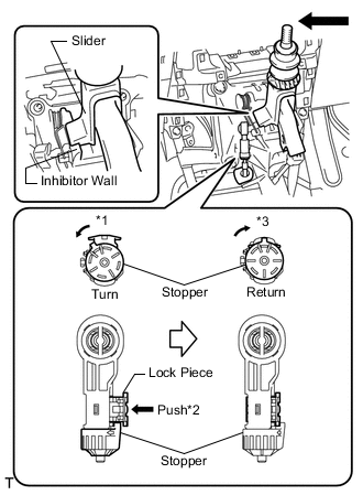
Connect the control select cable to the shift lever assembly.
-
Push the slider against the inhibitor wall.
Note
-
Do not pull up the slider.
-
When adjusting the cable, make sure that the shift lever is not in the 1 or 2.
-
-
Lock the cable length adjustment structure of the select cable.
-
Turn the stopper.*1
-
Push the lock piece into the case.*2
-
Return the stopper to prevent the lock from being released.*3
Note
-
Push the lock piece as far as it will go.
-
Confirm whether the cable length adjustment structure is locked securely.
-
-
-
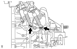
*1 Reverse Restrict Pin Assembly *2 Outer Lever *3 Release w/ Reverse Restrict Pin Assembly:
Move the shift lever to R to release the outer lever.
-
w/o Reverse Restrict Pin Assembly:
Pull out the bolt to free the outer lever.
-
-
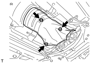
INSTALL FRONT NO. 1 FLOOR HEAT INSULATOR
-
Install the front No. 1 floor heat insulator with the 3 nuts.
- Torque:
- 5.5 N*m { 56 kgf*cm, 49 in.*lbf }
-
-
INSTALL LOWER NO. 1 INSTRUMENT PANEL FINISH PANEL
-
INSTALL AIR CLEANER CASE
-
INSTALL AIR CLEANER CAP SUB-ASSEMBLY
-
INSTALL BATTERY CARRIER
-
INSTALL BATTERY TRAY
-
INSTALL BATTERY
-
INSTALL BATTERY CLAMP SUB-ASSEMBLY
-
INSTALL NO. 2 CYLINDER HEAD COVER
-
CONNECT CABLE TO POSITIVE BATTERY TERMINAL
-
CONNECT CABLE TO NEGATIVE BATTERY TERMINAL
Note
When disconnecting the cable, some systems need to be initialized after the cable is reconnected Click here.
-
INSTALL FRONT EXHAUST PIPE ASSEMBLY
-
Install the front exhaust pipe assembly Click here.
-