CLUTCH RELEASE CYLINDER(for 1WW) INSTALLATION
PROCEDURE
-
INSTALL CLUTCH RELEASE CYLINDER KIT
-
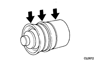
Coat a new piston with lithium soap base glycol grease as shown in the illustration.
-
Install the piston and a new spring to the release cylinder body.
Note
Do not damage the inside of the release cylinder body.
Tech Tips
Install the smaller end of the spring to the piston.
-
Install a new boot to the push rod.
-
Install the push rod together with the boot to the release cylinder body.
-
-
TEMPORARILY INSTALL RELEASE CYLINDER BLEEDER PLUG
-
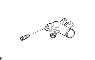
Install the release cylinder bleeder plug to the release cylinder body.
- Torque:
- 11 N*m { 112 kgf*cm, 8 ft.*lbf }
-
Install the bleeder plug cap to the bleeder plug.
-
-
INSTALL CLUTCH RELEASE CYLINDER ASSEMBLY
-
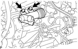
Install the clutch release cylinder assembly with the 2 bolts.
- Torque:
- 12 N*m { 122 kgf*cm, 9 ft.*lbf }
-
-
CONNECT CLUTCH RELEASE CYLINDER TO FLEXIBLE HOSE TUBE
-
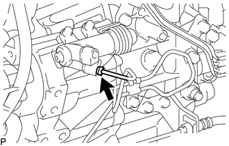
Using a union nut wrench, connect the clutch release cylinder to flexible hose tube.
- Torque:
- 15 N*m { 155 kgf*cm, 11 ft.*lbf }
Note
Use the formula to calculate special torque values for situations where a union nut wrench is combined with a torque wrench Click here.
-
-
BLEED CLUTCH LINE
-
INSPECT FLUID LEVEL
-
INSPECT FOR FLUID LEAK
Tech Tips
Check for leaks in the clutch system.
-
INSTALL NO.1 AIR TUBE ASSEMBLY
-
INSTALL BATTERY CARRIER ASSEMBLY
-
INSTALL BATTERY TRAY
-
INSTALL BATTERY
-
INSTALL BATTERY INSULATOR
-
INSTALL BATTERY CLAMP SUB-ASSEMBLY
-
CONNECT CABLE TO POSITIVE BATTERY TERMINAL
-
CONNECT CABLE TO NEGATIVE BATTERY TERMINAL
Note
When disconnecting the cable, some systems need to be initialized after the cable is reconnected Click here.
-
INSTALL AIR CLEANER CASE SUB-ASSEMBLY
-
INSTALL AIR CLEANER FILTER ELEMENT SUB-ASSEMBLY
-
INSTALL AIR CLEANER CAP SUB-ASSEMBLY WITH AIR CLEANER HOSE ASSEMBLY
-
ADD ENGINE COOLANT
-
INSPECT COOLANT LEAK
-
INSTALL NO.1 ENGINE UNDER COVER