STOP AND START SYSTEM, Diagnostic DTC:P323B
| DTC Code | DTC Name |
|---|---|
| P323B | Backup Boost Converter |
DESCRIPTION
Refer to DTC B22C0 Click here.
| DTC No. | DTC Detection Condition | Trouble Area |
|---|---|---|
| P323B | Any of the following conditions is met for 1 second or more (1 trip detection logic):
|
|
CONFIRMATION DRIVING PATTERN
-
CONFIRMATION AFTER TROUBLESHOOTING
Tech Tips
-
When the cable is disconnected from the negative (-) battery terminal, stop and start control is prohibited for a certain amount of time. After connecting the cable, drive the vehicle until stop and start control is permitted (approximately 15 to 40 minutes).
-
Allow the engine to idle for 3 minutes after the engine warms up and check that the engine speed is within 50 rpm of the target idle speed.
-
Connect the GTS to the DLC3.
-
Turn the ignition switch to ON and turn the GTS on.
-
Clear the DTCs Click here.
-
Start the engine and warm it up.
-
Drive the vehicle at 7 km/h (4.3 mph) or more.
CAUTION:
When performing the confirmation driving pattern, obey all speed limits and traffic laws.
-
Stop the vehicle, move the shift lever to neutral and release the clutch pedal.
-
Keep the engine stopped by stop and start control for 1 second or more.
-
Depress the clutch pedal and start the engine.
Tech Tips
If the engine cranks slowly when the engine is restarted, it can be determined that battery voltage is low.
-
Check that DTCs are not output Click here.
-
-
STOP AND START SYSTEM OPERATION CHECK
Tech Tips
When the cable is disconnected from the negative (-) battery terminal, stop and start control is prohibited for a certain amount of time. After connecting the cable, drive the vehicle until stop and start control is permitted (approximately 15 to 40 minutes).
-
Start the engine and warm it up.
-
Turn the air conditioning system off.
-
Drive the vehicle at 7 km/h (4.3 mph) or more.
CAUTION:
When performing the confirmation driving pattern, obey all speed limits and traffic laws.
-
Stop the vehicle, move the shift lever to neutral and release the clutch pedal.
-
Allow the engine to stop by stop and start control.
-
Depress the clutch pedal and start the engine.
-
WIRING DIAGRAM
Refer to DTC B22C0 Click here.
CAUTION / NOTICE / HINT
Note
-
Before replacing the engine stop and start ECU, read the number of starter operations and write it into a new engine stop and start ECU Click here.
-
After replacing the engine stop and start ECU or air conditioning amplifier assembly, reset and perform learning of the air conditioning information in the engine stop and start ECU Click here.
-
After replacing the engine stop and start ECU or yaw rate sensor, clear and calibrate the deceleration sensor zero point in the engine stop and start ECU Click here.
-
Inspect the fuses for circuits related to this system before performing the following procedure.
Tech Tips
Using the GTS, read the freeze frame data before troubleshooting. System condition information is recorded as freeze frame data the moment a DTC is stored. This information can be useful when troubleshooting Click here.
PROCEDURE
-
CHECK HARNESS AND CONNECTOR (ENGINE STOP AND START ECU - BBC FUSE)
-
Disconnect the A73 engine stop and start ECU connector.
-
Remove the BBC fuse from the engine room relay block and junction block assembly.
-
Measure the resistance according to the value(s) in the table below.
Standard Resistance Tester Connection Condition Specified Condition A73-7 (BIN) - BBC fuse terminal 2 Always Below 1 Ω A73-7 (BIN) - Body ground Always 10 kΩ or higher BBC fuse terminal 2 - Body ground Always 10 kΩ or higher
NG 
REPAIR OR REPLACE HARNESS OR CONNECTOR
OK 
-
-
CHECK HARNESS AND CONNECTOR (ENGINE STOP AND START ECU POWER SOURCE CIRCUIT)
-
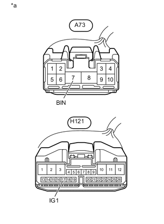
Text in Illustration *a Front view of wire harness connector
(to Engine Stop and Start ECU)
Disconnect the A73 and H121 engine stop and start ECU connectors.
-
Measure the voltage according to the value(s) in the table below.
Standard Voltage Tester Connection Condition Specified Condition A73-7 (BIN) - Body ground Always 9.5 to 14 V -
Turn the ignition switch to ON.
-
Measure the voltage according to the value(s) in the table below.
Standard Voltage Tester Connection Switch Condition Specified Condition H121-17 (IG1) - Body ground Ignition switch ON 9.5 to 14 V
NG
REPAIR OR REPLACE HARNESS OR CONNECTOR
OK
-
-
CHECK HARNESS AND CONNECTOR (ENGINE STOP AND START ECU - BODY GROUND)
-
Disconnect the A73 engine stop and start ECU connector.
-
Measure the resistance according to the value(s) in the table below.
Standard Resistance Tester Connection Condition Specified Condition A73-8 (GND) - Body ground Always Below 1 Ω
NG
REPAIR OR REPLACE HARNESS OR CONNECTOR
OK
-
-
CHECK HARNESS AND CONNECTOR (ENGINE STOP AND START ECU - EACH ECU OR SENSOR)
-
Disconnect the H121 engine stop and start ECU connector.
-
for Radio Receiver Type:
Disconnect the H1 radio receiver assembly connector.
-
for Radio and Display Receiver Type:
Disconnect the H107 radio and display receiver assembly connector.
-
Disconnect the DH instrument panel junction block assembly (main body ECU (multiplex network body ECU)).
-
Disconnect the A79 skid control ECU (brake actuator assembly) connector.
-
Disconnect the H68 yaw rate sensor connector.
-
Disconnect the H128 steering angle sensor (spiral with sensor cable sub-assembly) connector.
-
Disconnect the H49 power steering ECU assembly connector.
-
w/ Automatic Glare-resistant EC mirror:
Disconnect the Q9 inner rear view mirror assembly connector.
-
w/ TOYOTA Parking Assist-sensor System:
Disconnect the H97 back sonar or clearance sonar switch assembly connector.
-
w/ Tire Pressure Warning System:
Disconnect the N32 tire pressure warning ECU and receiver connector.
-
Measure the resistance according to the value(s) in the table below.
Standard Resistance Tester Connection Condition Specified Condition H121-2 (BO1) - H1-4 (+B1)*1 Always Below 1 Ω H121-2 (BO1) - H107-4 (+B1)*2 Always Below 1 Ω H121-12 (IGO1) - A79-4 (IG1) Always Below 1 Ω H121-12 (IGO1) - H49-5 (IG) Always Below 1 Ω H121-12 (IGO1) - DH-13 (IG) Always Below 1 Ω H121-12 (IGO1) - H128-5 (IG) Always Below 1 Ω H121-12 (IGO1) - H68-1 (IGA) Always Below 1 Ω H121-12 (IGO1) - Q9-4 (IG)*3 Always Below 1 Ω H121-12 (IGO1) - H97-6 (IG)*4 Always Below 1 Ω H121-12 (IGO1) - N32-1 (IG)*5 Always Below 1 Ω H121-2 (BO1) - Body ground Always 10 kΩ or higher H121-12 (IGO1) - Body ground Always 10 kΩ or higher
-
*1: for Radio Receiver Type
-
*2: for Radio and Display Receiver Type
-
*3: w/ Automatic Glare-resistant EC Mirror
-
*4: w/ TOYOTA Parking Assist-sensor System
-
*5: w/ Tire Pressure Warning System
-
OK
REPLACE ENGINE STOP AND START ECU Click here
NG
REPAIR OR REPLACE HARNESS OR CONNECTOR
-