LANE DEPARTURE ALERT SYSTEM Lane Departure Alert System Circuit
DESCRIPTION
When the ignition switch is ON, power is supplied to the pre-collision city sensor.
WIRING DIAGRAM
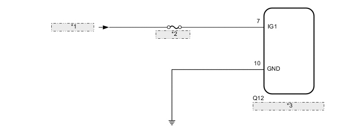
| *1 | from IG Circuit |
| *2 | ECU-IG NO. 3 |
| *3 | Pre-collision City Sensor |
CAUTION / NOTICE / HINT
Note
Inspect the fuses for circuits related to this system before performing the following procedure.
PROCEDURE
-
INSPECT BATTERY VOLTAGE
-
Measure the battery voltage with the ignition switch off.
Standard voltage 11 to 14 V -
Using the parts location and system diagram, check the system for blown-out fuses, open or short circuits in the wire harness(es) and connectors that are not properly connected by performing a visual check.
Tech Tips
If the voltage is 11 V or less, replace or recharge the battery before proceeding to the next step.
NEXT 
-
-
CHECK PRE-COLLISION CITY SENSOR
-
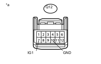
Text in Illustration *a Front view of wire harness connector
(to Pre-collision City Sensor)
Disconnect the pre-collision city sensor connector.
-
Measure the voltage according to the value(s) in the table below.
Standard Voltage Tester Connection Condition Specified Condition Q12-7 (IG1) - Body ground Ignition switch ON 11 to 14 V Q12-7 (IG1) - Body ground Ignition switch off Below 1 V -
Measure the resistance according to the value(s) in the table below.
Standard Resistance Tester Connection Condition Specified Condition Q12-10 (GND) - Body ground Always Below 1 Ω
NG 
REPAIR OR REPLACE HARNESS OR CONNECTOR
OK
-
-
CHECK CAN COMMUNICATION SYSTEM
-
Use the GTS to check if the CAN communication system is functioning normally Click here.
Result Result Proceed to CAN communication system DTCs are not output A CAN communication system DTCs are output B
A
PROCEED TO NEXT SUSPECTED AREA SHOWN IN PROBLEM SYMPTOMS TABLE Click here
B
GO TO CAN COMMUNICATION SYSTEM Click here
-