SPEED LIMITER SYSTEM TERMINALS OF ECM
-
CHECK ECM (for 1ZR-FAE, 2ZR-FAE)
-
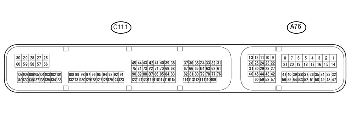
Disconnect the A76 and C111 ECM connectors.
-
Measure the voltage and resistance according to the value(s) in the table below.
Terminal No. (Symbol) Wiring Color Terminal Description Condition Specified Condition A76-1 (BATT) - Body ground P - Body ground Power source circuit Always 11 to 14 V A76-6 (IGSW) - Body ground B - Body ground IG power source circuit Ignition switch ON 11 to 14 V Ignition switch off Below 1 V A76-20 (ASLM) - Body ground GR - Body ground Speed limiter main switch signal Speed limiter main switch on Below 1 Ω Speed limiter main switch off 10 kΩ or higher C111-59 (E1) - Body ground BR - Body ground Ground Always Below 1 Ω If the result is not as specified, there may be a malfunction on the wire harness side.
-
-
CHECK ECM (for 1WW)
-
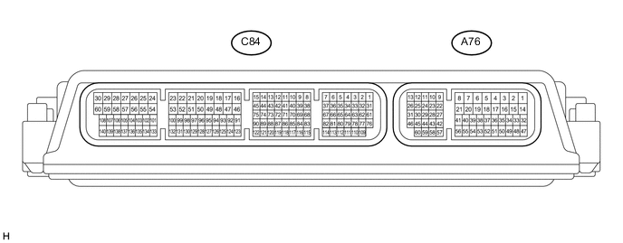
Disconnect the A76 ECM connectors.
-
Measure the voltage and resistance according to the value(s) in the table below.
Terminal No. (Symbol) Wiring Color Terminal Description Condition Specified Condition A76-15 (BATT) - Body ground B - Body ground Power source circuit Always 11 to 14 V A76-37 (B) - Body ground B - Body ground IG power source circuit Ignition switch ON 11 to 14 V Ignition switch off Below 1 V A76-49 (ASLM) - Body ground GR - Body ground Speed limiter main switch signal Speed limiter main switch on Below 1 Ω Speed limiter main switch off 10 kΩ or higher A76-4 (E1) - Body ground W-B - Body ground Ground Always Below 1 Ω If the result is not as specified, there may be a malfunction on the wire harness side.
-