CRUISE CONTROL SYSTEM(except 1WW) Cruise Control Switch Circuit
DESCRIPTION
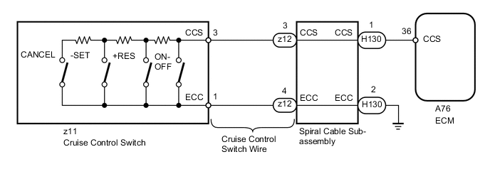
This circuit sends a signal to the ECM depending on the cruise control switch condition. The battery supplies positive (+) battery voltage to the cruise control switch. Terminal 36 (CCS) of the ECM receives the voltage which varies according to the switch condition.
WIRING DIAGRAM
PROCEDURE
-
READ VALUE USING INTELLIGENT TESTER (CRUISE CONTROL SWITCH)
-
Use the Data List to check if the cruise control switch is functioning properly.
Cruise Control Tester Display Measurement Item/Range Normal Condition Diagnostic Note Main SW M-CPU Cruise control switch (Main CPU) / ON or OFF ON: Cruise control switch on
OFF: Cruise control switch off
- Cancel Switch CANCEL switch signal / ON or OFF ON: CANCEL switch on
OFF: CANCEL switch off
- SET/COAST Switch -SET switch signal / ON or OFF ON: -SET switch on
OFF: -SET switch off
- RES/ACC Switch +RES switch signal / ON or OFF ON: +RES switch on
OFF: +RES switch off
- OK On screen, each item changes between ON and OFF according to above chart.
OK 
PROCEED TO NEXT SUSPECTED AREA SHOWN IN PROBLEM SYMPTOMS TABLE Click here
NG 
-
-
INSPECT SPIRAL CABLE SUB-ASSEMBLY
-
Remove the spiral cable with sensor sub-assembly Click here.
-
Inspect the spiral cable with sensor sub-assembly Click here.
NG
REPLACE SPIRAL CABLE SUB-ASSEMBLY Click here
OK
-
-
INSPECT CRUISE CONTROL SWITCH WIRE
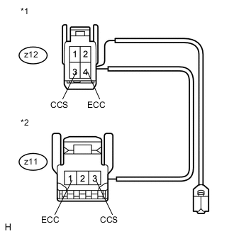
Text in Illustration *1 Front view of wire harness connector
(to Spiral Cable)
*2 Front view of wire harness connector
(to Cruise Control Switch)
-
Disconnect the z12 spiral cable connector.
-
Disconnect the z11 switch connector.
-
Measure the resistance according to the value(s) in the table below.
Standard Resistance Tester Connection Condition Specified Condition z12-3 (CCS) - z11-3 (CCS) Always Below 1 Ω z12-4 (ECC) - z11-1 (ECC) z12-3 (CCS) - Body ground Always 10 kΩ or higher z12-4 (ECC) - Body ground
NG
REPLACE CRUISE CONTROL SWITCH WIRE
OK
-
-
INSPECT CRUISE CONTROL SWITCH
-
Remove the cruise control switch Click here.
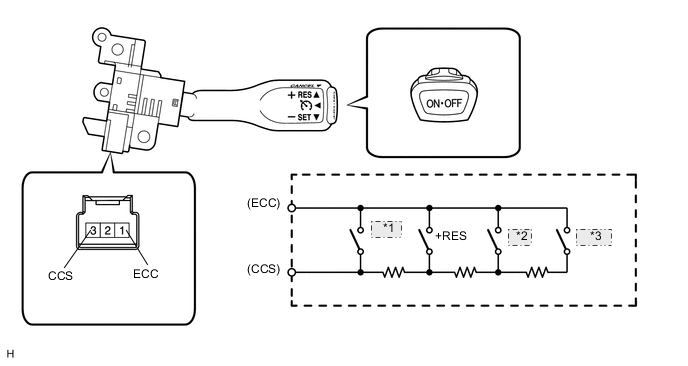
*1 ON-OFF *2 -SET *3 CANCEL -
Measure the resistance according to the value(s) in the table below.
Standard Resistance Tester Connection Switch Condition Specified Condition 3 (CCS) - 1 (ECC) Cruise control switch on Below 2.5 Ω Cruise control switch off 1 MΩ or higher +RES switch held on 235 to 245 Ω +SET switch held on 617 to 643 Ω CANCEL switch held on 1509 to 1571 Ω
NG
REPLACE CRUISE CONTROL SWITCH Click here
OK
-
-
CHECK HARNESS AND CONNECTOR (SPIRAL CABLE SUB-ASSEMBLY - ECM AND BODY GROUND)
-
Disconnect the H130 spiral cable connector.
-
Disconnect the A76 ECM connector.
-
Measure the resistance according to the value(s) in the table below.
Standard Resistance Tester Connection Condition Specified Condition H130-1 (CCS) - A76-36 (CCS) Always Below 1 Ω H130-2 (ECC) - Body ground H130-1 (CCS) - Body ground Always 10 kΩ or higher Result Result Proceed to OK (for 1ZR-FAE) A OK (for 2ZR-FAE) B NG C
A
REPLACE ECM Click here
B
REPLACE ECM Click here
C
REPAIR OR REPLACE HARNESS OR CONNECTOR
-