IGNITION SWITCH INSPECTION
PROCEDURE
-
INSPECT IGNITION SWITCH ASSEMBLY
-
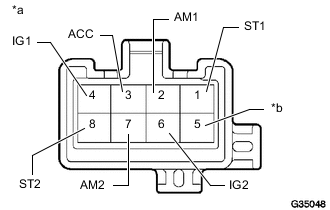
Text in Illustration *a Component without harness connected:
(Ignition Switch Assembly)
*b No Pin Measure the resistance according to the value(s) in the table below.
Standard Resistance Tester Connection Switch Condition Specified Condition All combinations of all terminals LOCK 10 kΩ or higher 2 (AM1) - 3 (ACC) ACC Below 1 Ω 2 (AM1) - 3 (ACC)
2 (AM1) - 4 (IG1)
6 (IG2) - 7 (AM2)
ON Below 1 Ω 1 (ST1) - 2 (AM1)
1 (ST1) - 4 (IG1)
6 (IG2) - 7 (AM2)
6 (IG2) - 8 (ST2)
START Below 1 Ω If the result is not as specified, replace the ignition switch assembly.
-