MONOLITHIC CONVERTER INSTALLATION
CAUTION / NOTICE / HINT
Tech Tips
Perform "Inspection After Repair" after replacing the exhaust manifold converter sub-assembly Click here.
PROCEDURE
-
INSTALL EXHAUST MANIFOLD CONVERTER SUB-ASSEMBLY
Tech Tips
Perform "Inspection After Repair" after replacing the exhaust manifold converter sub-assembly Click here.
-
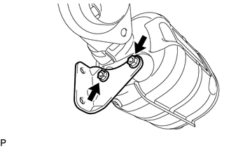
Temporarily install the manifold stay with the 2 nuts.
-
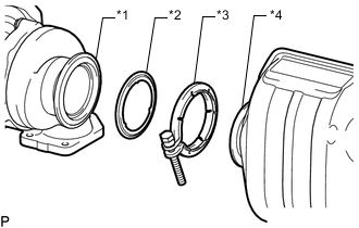
Text in Illustration *1 Turbocharger Sub-assembly *2 Gasket *3 V-band Clamp *4 Exhaust Manifold Converter Sub-assembly Temporarily install the exhaust manifold converter sub-assembly and engine bracket with the 3 nuts, 3 bolts, new V-band clamp and new gasket.
-
Tighten the engine bracket with the 3 bolts.
- Torque:
- 19 N*m { 194 kgf*cm, 14 ft.*lbf }
-
Temporarily install the manifold stay with the 2 bolts.
-
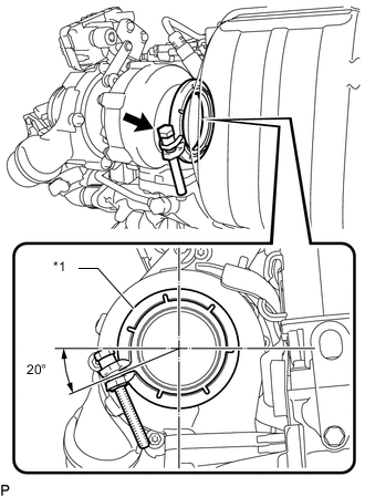
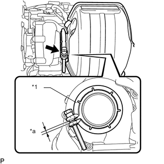
Text in Illustration *1 V-band Clamp Align the V-band clamp as shown in the illustration and temporarily install it.
- Torque:
- 3.0 N*m { 31 kgf*cm, 27 in.*lbf }
Tech Tips
To prevent the V-band clamp from interfering with the No. 1 manifold converter insulator, temporarily install the V-band clamp at the angle shown in the illustration.
-
Text in Illustration *1 V-band Clamp *a Clearance Tighten the V-band clamp.
- Torque:
- 15 N*m { 153 kgf*cm, 11 ft.*lbf }
-
Check the clearance of the V-band clamp.
Note
Do not reuse a V-band clamp that has been tightened to the specified torque.
Tech Tips
After tightening the V-band clamp to the specified torque, check that the clearance is within 0 to 3.5 mm (0 to 0.138 in.). If the result is not as specified, reinstall the exhaust manifold converter sub-assembly as the installation position is incorrect.
-
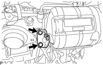
Tighten the 5 nuts, 2 bolts and exhaust manifold converter sub-assembly in the order shown in the illustration.
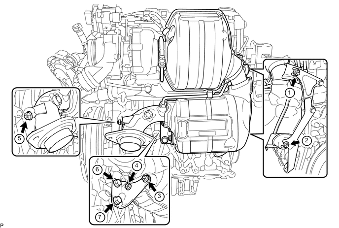
- Torque:
- for bolt
- 38 N*m { 387 kgf*cm, 28 ft.*lbf }
- for nut
- 19 N*m { 194 kgf*cm, 14 ft.*lbf }
-
-
INSTALL NO. 1 EXHAUST MANIFOLD HEAT INSULATOR
-
Install the No. 1 exhaust manifold heat insulator with the 2 bolts.
- Torque:
- 8.0 N*m { 82 kgf*cm, 71 in.*lbf }
-
Attach the 2 clamps and connect the engine wire.
-
-
INSTALL FRONT EXHAUST PIPE ASSEMBLY
-
Check the free length of the compression spring.
-
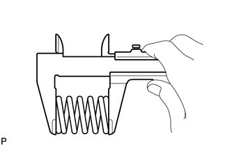
Using a vernier caliper, measure the free length of the compression spring.
Minimum length 41.5 mm (1.63 in.) If the free length is less than the minimum, replace the compression spring.
-
-
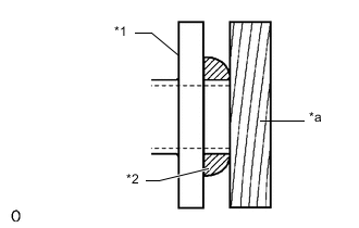
Text in Illustration *1 Exhaust Manifold Converter Sub-assembly *2 Gasket *a Wooden Block Using a plastic-faced hammer and wooden block, tap in a new gasket until its surface is flush with the exhaust manifold converter sub-assembly.
Note
-
Be sure to install the gasket so that it faces the correct direction.
-
Do not reuse the gasket.
-
Do not damage the gasket.
-
When connecting the exhaust pipe, do not push in the gasket with the exhaust pipe.
-
-
Install a new gasket to the front exhaust pipe assembly.
-
Connect the front exhaust pipe assembly to the 3 exhaust pipe supports.
-
Install the front exhaust pipe assembly with the 4 bolts and 4 compression springs.
- Torque:
- 43 N*m { 438 kgf*cm, 32 ft.*lbf }
-
-
INSTALL FRONT FLOOR CENTER BRACE
-
INSTALL NO. 2 ENGINE UNDER COVER
-
INSTALL OUTER COWL TOP PANEL
-
INSTALL WINDSHIELD WIPER MOTOR ASSEMBLY
-
INSTALL HEATER WITH EXHAUST PIPE ASSEMBLY (w/ Combustion Type Power Heater)
-
INSTALL DIFFERENTIAL PRESSURE SENSOR
-
INSTALL EXHAUST GAS TEMPERATURE SENSOR
-
for Sensor 1: Click here
-
for Sensor 2: Click here
-
-
INSTALL AIR FUEL RATIO SENSOR
-
for Sensor 1: Click here
-
for Sensor 2: Click here
-
-
INSPECT FOR EXHAUST GAS LEAK
-
PERFORM INITIALIZATION
-
Perform DPF history information reset Click here.
-
Perform NOx storage catalyst learning value reset Click here.
-