FUEL PUMP INSTALLATION
PROCEDURE
-
INSTALL FUEL SENDER GAUGE ASSEMBLY
-
INSTALL FUEL SUCTION WITH PUMP AND GAUGE TUBE ASSEMBLY
-
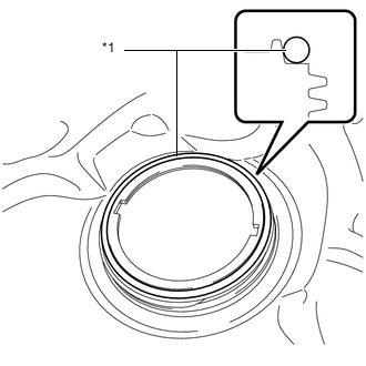
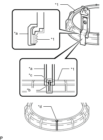
*1 Gasket Apply a light coat of fuel to a new gasket and install the gasket to the fuel tank assembly.
-
Install the fuel suction with pump and gauge tube assembly to the fuel tank assembly.
Note
Make sure that the fuel sender gauge assembly arm does not bend.
-
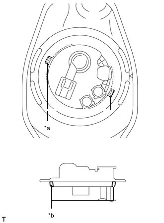
*a Notch *b Protrusion Align the protrusions of the fuel suction with pump and gauge tube assembly with the notches of the fuel tank assembly.
-
-
INSTALL FUEL PUMP GAUGE RETAINER
-
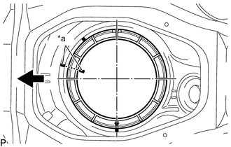
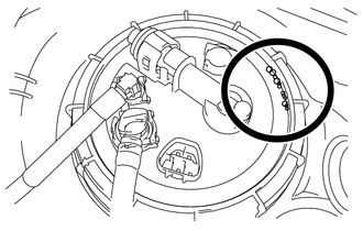
*a Co-rotation Prevention Check Mark 
Front Side of Vehicle Apply a co-rotation prevention check mark to the fuel suction with pump and gauge tube assembly.
Tech Tips
Perform this step only when replacing the fuel suction with pump and gauge tube assembly.
-
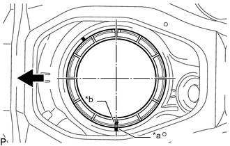
*a Start Mark (Fuel Tank Assembly) *b Start Mark (Fuel Pump Gauge Retainer) Front Side of Vehicle Put the fuel pump gauge retainer on the fuel tank assembly. While holding the fuel suction with pump and gauge tube assembly, tighten the fuel pump gauge retainer one complete turn by hand.
Note
Replace the fuel pump gauge retainer with a new one if not installed properly.
Tech Tips
Make sure the start marks on the fuel pump gauge retainer and fuel tank assembly are aligned, and then tighten the fuel pump gauge retainer.
-
*1 Fuel Pump Gauge Retainer *a SST (Claw Set) *b Rib *c Cutout *d SST (Claw Set) Incorrect Installation Point (Rotational Start Point Mark of Fuel Pump Gauge Retainer) Install SST to the fuel pump gauge retainer.
-
Set 4 SST (claw set) to the fuel pump gauge retainer.
- SST
- 09808-14031 ( 09808-01080, 09808-01090, 09808-01100 )
Note
-
Align the notch of SST (claw set) with the protrusion of the fuel pump gauge retainer.
-
Do not place SST on the rotational start point mark of the fuel pump gauge retainer, otherwise SST (claw set) cannot be set correctly.
-
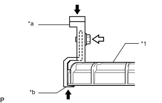
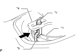
*1 Fuel Pump Gauge Retainer *a SST (Claw Set) *b Hook Press 
SST (Bolt) While firmly pressing the claw of SST into rib of the fuel pump gauge retainer, tighten the bolt.
-
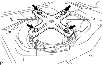
*a SST (Plate) *b SST (Claw Set) SST (Bolt) Temporarily install SST (plate) to SST (claw set) with 4 SST (bolt).
- SST
- 09808-14031 ( 09808-01030, 09808-01090 )
-
*a Center Point of Fuel Pump Gauge Retainer *b SST (Plate) Front Side of Vehicle Adjust the position of SST (claw set) so that the hole in SST (plate) for installing SST (handle) is in the center of the fuel pump gauge retainer.
-
*1 Fuel Pump Gauge Retainer *a SST (Plate) *b SST (Claw Set) *c SST (Bolt) Press Press SST (claw set) against the rib of the fuel pump gauge retainer and tighten SST (bolt).
-
-
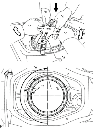
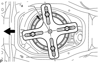
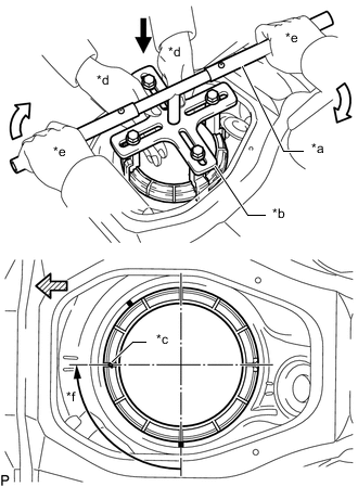
*a SST (Plate) *b Start Mark (Fuel Pump Gauge Retainer) *c Worker A *d Worker B *e Approximately 180° *f Co-rotation Prevention Check Mark Press Down Slowly Rotate 
Front Side of Vehicle While one person presses down to prevent the fuel pump gauge retainer and the fuel suction with pump and gauge tube assembly from rotating together, the other person should firmly press the fuel pump gauge retainer against the threads of the fuel tank assembly, and tighten it by rotating it approximately 180°.
CAUTION:
Make sure not to pinch your hands with SST.
Note
-
Be careful not to apply excessive downward force to SST, as this may damage the fuel suction with pump and gauge tube assembly or fuel tank assembly.
-
Turning SST at an angle may cause it to slip off of the fuel pump gauge retainer, so make sure SST is horizontal when turning it.
-
To prevent damage to parts, do not turn SST too vigorously.
-
Do not rotate the fuel pump gauge retainer when the co-rotation prevention check mark is out of place.
-
-
As shown in the illustration, quickly and firmly press down on the part of the fuel pump gauge retainer closest to the front side of the vehicle so that it no longer rises up.
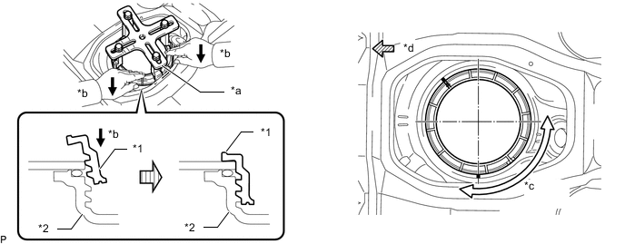
*1 Fuel Pump Gauge Retainer *2 Fuel Tank Assembly *a SST (Plate) *b Press Quickly and Firmly *c Fuel Pump Gauge Retainer Rise Up Area *d Front Side of Vehicle Tech Tips
-
If the fuel pump gauge retainer cannot be properly pressed down due to the position of SST, set SST in a different position.
-
When pressing down the fuel pump gauge retainer, there will be a sound or feeling of parts contacting and pressing together when the fuel pump gauge retainer is fully pressed down, and at this point it will stop rising up.
-
-
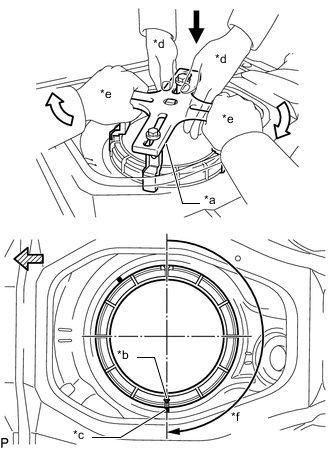
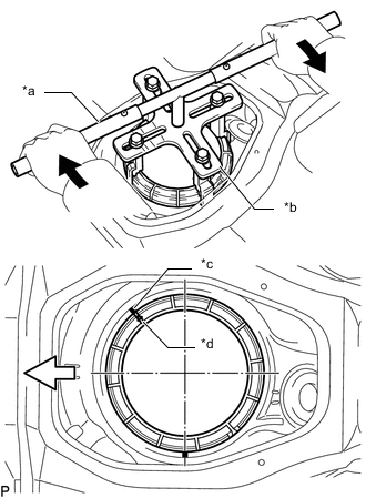
*a SST (Plate) *b Start Mark (Fuel Pump Gauge Retainer) *c Start Mark (Fuel Tank Assembly) *d Worker A *e Worker B *f Rotate to Start Mark on Fuel Tank Assembly Press Down Slowly Rotate Front Side of Vehicle While one person presses down to prevent the fuel pump gauge retainer and the fuel suction with pump and gauge tube assembly from rotating together, the other person should slowly rotate SST (plate) and tighten the fuel pump gauge retainer until it reaches the start mark on the fuel tank assembly.
CAUTION:
Make sure not to pinch your hands with SST.
-
Check the tightening condition of the fuel pump gauge retainer.
-
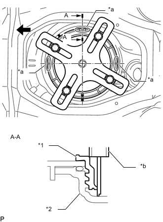
*1 Fuel Pump Gauge Retainer *2 Fuel Tank Assembly *a Measurement Location *b Vernier Caliper Front Side of Vehicle Using a vernier caliper, measure the upper surface of the fuel tank assembly in the 3 locations shown in the illustration.
Specification Difference between the 3 measured values is within 3.0 mm (0.118 in.). Note
If the difference between measurements is approximately 6.0 mm (0.236 in.), the threads are cross-threaded by one row (6.0 mm (0.236 in.)), so remove and reinstall the fuel pump gauge retainer.
-
-
*a SST (Handle) *b SST (Plate) *c Start Mark (Fuel Pump Gauge Retainer) *d Worker A *e Worker B *f Approximately 90° Press Down Slowly Rotate Front Side of Vehicle Install SST (handle) to SST (plate).
- SST
- 09808-14031 ( 09808-01010, 09808-01020 )
-
While one person presses down to prevent the fuel pump gauge retainer and the fuel suction with pump and gauge tube assembly from rotating together, the other person should slowly rotate SST (handle) and tighten the fuel pump gauge retainer by approximately 90°.
CAUTION:
Make sure not to pinch your hands with SST.
-
*a SST (Handle) *b SST (Plate) *c Copy of Fully Tightened Mark *d Start of Threads of the Fuel Pump Gauge Retainer Tighten Front Side of Vehicle Slowly tighten the fuel pump gauge retainer until it reaches the fully tightened mark that was copied onto the vehicle body.
-
-
INSTALL TANK SUCTION TUBE SUPPORT
-
Attach the 2 claws to install the tank suction tube support.
-
-
CONNECT NO. 2 FUEL TANK MAIN TUBE SUB-ASSEMBLY (w/ Combustion Type Power Heater)
-
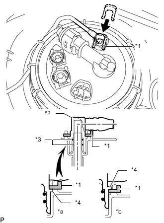
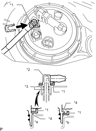
*1 Tube Joint Clip *2 Fuel Tube Joint *3 O-Ring *4 Collar *a CORRECT *b INCORRECT Push the fuel tube joint into the plug of the fuel suction with pump and gauge tube assembly, and then install the tube joint clip.
Note
-
Check that there are no scratches or foreign objects on the connecting parts.
-
Check that the fuel tube joint is inserted securely.
-
Check that the tube joint clip is on the collar of the fuel tube joint.
-
After installing the tube joint clip, check that the fuel tube joint cannot be pulled off.
-
-
-
CONNECT FUEL TANK MAIN TUBE SUB-ASSEMBLY
-
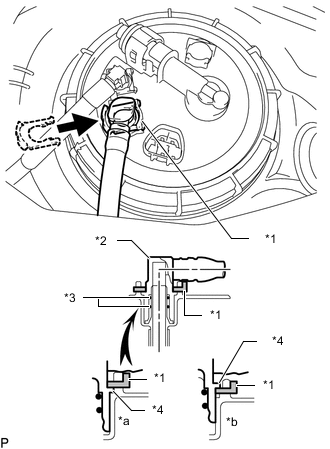
*1 Tube Joint Clip *2 Fuel Tube Joint *3 O-Ring *4 Collar *a CORRECT *b INCORRECT Push the fuel tube joint into the plug of the fuel suction with pump and gauge tube assembly, and then install the tube joint clip.
Note
-
Check that there are no scratches or foreign objects on the connecting parts.
-
Check that the fuel tube joint is inserted securely.
-
Check that the tube joint clip is on the collar of the fuel tube joint.
-
After installing the tube joint clip, check that the fuel tube joint cannot be pulled off.
-
-
-
CONNECT FUEL TANK RETURN TUBE SUB-ASSEMBLY
-
*1 Tube Joint Clip *2 Fuel Tube Joint *3 O-Ring *4 Collar *a CORRECT *b INCORRECT Push the fuel tube joint into the plug of the fuel suction with pump and gauge tube assembly, and then install the tube joint clip.
Note
-
Check that there are no scratches or foreign objects on the connecting parts.
-
Check that the fuel tube joint is inserted securely.
-
Check that the tube joint clip is on the collar of the fuel tube joint.
-
After installing the tube joint clip, check that the fuel tube joint cannot be pulled off.
-
-
-
CHECK AIRTIGHTNESS
-
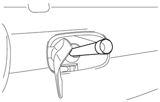
After installing the fuel suction tube, check for fuel leaks by first applying soapy water to the area where the suction plate and retainer contact, and then blow your breath forcefully through a flexible pouring spout or similar tube into the fuel inlet area.
-
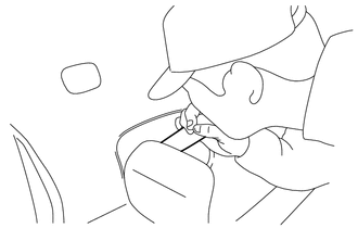
Blow forcefully until the reverse flow prevention valve inside the fuel inlet activates.
Note
Be careful not to inhale any fuel vapor.
Tech Tips
There should be a faintly audible sound when the reverse flow prevention valve operates.
-
-
If improper installation of the fuel suction with pump and gauge tube assembly, etc. has resulted in a condition where fuel will leak, air will leak out as shown in the illustration.
Note
If air leaks out, recheck the installation condition, and replace the used fuel pump gauge retainer and gasket with new ones. Also, make sure to fully clean away the soapy water. (Any remaining soapy water can cause the gasket to slip and result in an improper assembly.)
-
-
INSTALL REAR FLOOR SERVICE HOLE COVER
-
Connect the fuel suction with pump and gauge tube assembly connector.
-
Install the rear floor service hole cover with new butyl tape.
Note
Be careful that the rear floor service hole cover does not overlap the protrusions of the floor panel when installing.
-
-
INSPECT FOR FUEL LEAK
-
INSTALL REAR CENTER SEAT ASSEMBLY (w/ Rear No. 1 Seat)
-
INSTALL REAR NO. 1 SEAT ASSEMBLY (w/ Rear No. 1 Seat)