TRANSMISSION CONTROL CABLE INSTALLATION
CAUTION / NOTICE / HINT
Tech Tips
-
Use the same procedure for RHD and LHD vehicles.
-
The procedure listed below is for LHD vehicles.
PROCEDURE
-
INSTALL NO. 1 TRANSMISSION CONTROL CABLE BRACKET
-
Install the No. 1 transmission control cable bracket to the continuously variable transaxle assembly with the 2 bolts.
- Torque:
- 12 N*m { 122 kgf*cm, 9 ft.*lbf }
-
Attach the clamp.
-
-
INSTALL TRANSMISSION CONTROL CABLE ASSEMBLY
Note
Before installing the transmission control cable assembly, check that the park/neutral position switch and shift lever are in neutral.
-
Put the transmission control cable assembly into the cabin and connect the transmission control cable assembly with the 2 nuts.
- Torque:
- 5.0 N*m { 51 kgf*cm, 44 in.*lbf }
-
Connect the transmission control cable clamp to the rear engine mounting insulator with the bolt.
- Torque:
- 5.0 N*m { 51 kgf*cm, 44 in.*lbf }
-
Connect the transmission control cable assembly to the No. 1 transmission control cable bracket with a new clip.
-
Connect the transmission control cable assembly to the control shaft lever with the nut.
- Torque:
- 12 N*m { 122 kgf*cm, 9 ft.*lbf }
-
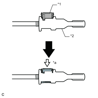
Turn the nut of the transmission control cable assembly 180° counterclockwise. While holding the nut in place, push in the stopper until the stopper clicks twice.
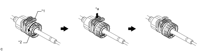
Text in Illustration *1 Stopper *2 Nut *a Push in - - -
Install the outer part of the transmission control cable assembly to the shift lever assembly. Check that the spring is positioned at "A" and push in the stopper.
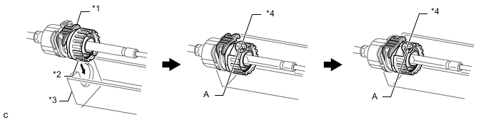
Text in Illustration *1 Stopper *2 Nut *3 Shift Lever Assembly *4 Spring Tech Tips
If the stopper cannot be pushed in, slightly turn the nut clockwise and then push in the stopper again.
-
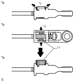
Text in Illustration *1 Lock Piece *a Side View *b Bottom View *c Push Push the 2 claws together at the top of the transmission control cable lock piece. While holding the 2 claws together, push the 2 lugs on the bottom of the lock piece toward each other and upward to pull out the lock piece.
-
Text in Illustration *1 Lock Piece 
MP grease Coat the end of the transmission control cable assembly with MP grease.
-
Connect the end of the transmission control cable assembly to the shift lever assembly.
Note
-
Make sure that the lock piece is pulled up.
-
Push on the end of the transmission control cable assembly all the way to the base of the pin.
-
-
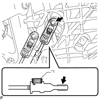
Text in Illustration *1 Lock Piece *2 Adjuster Case *a Push in Push the lock piece into the adjuster case.
Note
Securely push in the lock piece until it locks.
-
-
INSTALL FRONT FLOOR NO. 1 HEAT INSULATOR
-
Install the front floor No. 1 heat insulator with the 3 nuts.
- Torque:
- 5.5 N*m { 56 kgf*cm, 49 in.*lbf }
-
-
INSTALL FRONT FLOOR NO. 2 HEAT INSULATOR
-
Install the front floor No. 2 heat insulator with the 3 nuts.
- Torque:
- 5.5 N*m { 56 kgf*cm, 49 in.*lbf }
-
-
INSTALL FRONT EXHAUST PIPE ASSEMBLY
-
CONNECT HEATED OXYGEN SENSOR CONNECTOR
-
Attach the clamp.
-
Connect the connector.
-
-
INSTALL NO. 2 ENGINE UNDER COVER
-
INSTALL FRONT FLOOR CENTER BRACE
-
INSTALL AIR CLEANER CASE SUB-ASSEMBLY
-
INSTALL AIR CLEANER FILTER ELEMENT SUB-ASSEMBLY
-
INSTALL AIR CLEANER CAP SUB-ASSEMBLY
-
INSTALL NO. 2 CYLINDER HEAD COVER
-
INSPECT SHIFT LEVER POSITION
-
ADJUST SHIFT LEVER POSITION
-
INSTALL LOWER NO. 1 INSTRUMENT PANEL FINISH PANEL