WIPER AND WASHER SYSTEM Headlight Cleaner Switch Circuit
CAUTION / NOTICE / HINT
Note
Inspect the fuses for circuits related to this system before performing the following procedure.
DESCRIPTION
This circuit detects the conditions of the headlight cleaner switch.
-
Headlight cleaner switch signal
-
Headlight operating signal
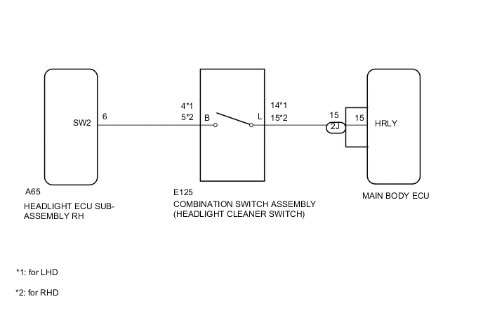
WIRING DIAGRAM
PROCEDURE
-
CHECK HEADLIGHT ASSEMBLY (LO BEAM)
-
Check that the headlights illuminate in LO beam.
OK Headlights illuminate in LO beam
NG 
GO TO LIGHTING SYSTEM Click here
OK 
-
-
INSPECT COMBINATION SWITCH ASSEMBLY (HEADLIGHT CLEANER SWITCH)
-
Remove the combination switch assembly (headlight cleaner switch ) Click here.
-
Inspect the combination switch assembly (headlight cleaner switch ) Click here.
NG
REPLACE COMBINATION SWITCH ASSEMBLY (HEADLIGHT CLEANER SWITCH) Click here
OK
-
-
CHECK HARNESS AND CONNECTOR (COMBINATION SWITCH - HEADLIGHT ECU SUB-ASSEMBLY AND MAIN BODY ECU)
-
Disconnect the E125 combination switch connector.
-
Disconnect the A65 headlight ECU connector.
-
Disconnect the 2J main body ECU connector.
-
Measure the resistance according to the value(s) in the table below.
Standard Resistance Tester Connection Condition Specified Condition A65-6 (SW2) - E125- (B) Always Below 1 Ω E125-14 (L) - 2J-15 (HRLY) A65-6 (SW2) - Body ground Always 10 kΩ or higher E125- (B) - Body ground E125-14 (L) - Body ground 2J-15 (HRLY) - Body ground
OK
GO TO PROCEED TO NEXT INSPECTION PROCEDURE SHOWN IN PROBLEM SYMPTOMS TABLE
NG
REPAIR OR REPLACE HARNESS OR CONNECTOR
-