WIPER AND WASHER SYSTEM TERMINALS OF ECU
-
CHECK WINDSHIELD WIPER RELAY
-
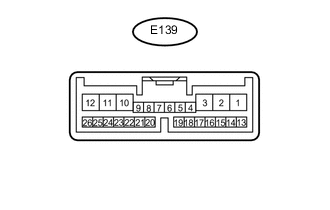
Disconnect the E139 windshield wiper relay connectors.
-
Measure the voltage and resistance according to the value(s) in the table below.
Terminal No. (Symbol) Wiring Color Terminal Description Condition Specified Condition E139-2 (IG) - Body ground B - Body ground IG power supply Engine switch on (IG) 11 to 14 V Engine switch off Below 1 V E139-8 (VR2) - E139-21 (VR1) W -R Adjust volume circit Windshield wiper switch adjusting ring changed 0 to 231 Ω E139-12 (E) - Body ground W-B - Body ground Body ground Always Below 1 Ω E139-16 (WIG) - Body ground B - Body ground IG power supply Engine switch on (IG) 11 to 14 V Engine switch off Below 1 V -
Reconnect the E139 windshield wiper relay connectors.
-
Measure the voltage according to the value(s) in the table below.
Terminal No. (Symbol) Wiring Color Terminal Description Condition Specified Condition E139-1 (+SM) - Body ground W - Body ground Front wiper motor operation signal Front wiper is operated 11 to 14 V Front wiper is stopped Below 1 V E139-3 (C1) - E139-5 (CO) L - R Windshield wiper assembly AUTO position signal Windshield wiper assembly in AUTO position Below 1 V Windshield wiper assembly in not AUTO position 11 to 14 V E139-10 (+1) - Body ground W - Body ground Front wiper motor low speed signal Front wiper motor in low operation 11 to 14 V Front wiper motor not operation 11 to 14 V E139-11 (+2) - Body ground R - Body ground Front wiper motor high speed signal Front wiper motor in high operation Below 1 V Front wiper motor not operation Below 1 V E139-14 (MPX1) - Body ground B - Body ground LIN communication signal Engine switch on (IG) Below 1 V E139-25 (W) - Body ground L - Body ground Front washer motor signal Front washer switch off 11 to 14 V Front washer switch on Below 1 V
-
-
CHECK NO. 2 MAIN BODY ECU
-
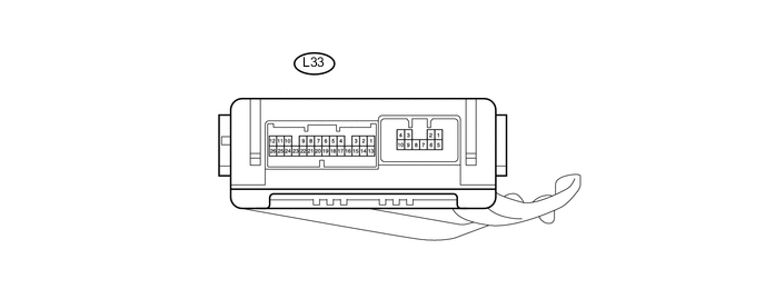
Disconnect the L33 ECU connector.
-
Measure the voltage and resistance according to the value(s) in the table below.
Terminal No. (Symbol) Wiring Color Terminal Description Condition Specified Condition L33-14 (BECU) - L33-7 (GND) R - W-B Power source Always 11 to 14 V L33-13 (SIG) - L33-7 (GND) G - W-B Power source Engine switch on (IG) 11 to 14 V L33-7 (GND) - Body ground W-B - Body ground Power source Always Below 1 Ω If the result is not as specified, there may be a malfunction on the wire harness side.
-
Reconnect the L33 ECU connector.
-
Measure the voltage according to the value(s) in the table below.
Terminal No. (Symbol) Wiring Color Terminal Description Condition Specified Condition L33-1 (RWSM) - Body ground G - Body ground Rear wiper motor operation signal Rear wiper operated 11 to 14 V Rear wiper stopped Below 1 V L33-4 (WRLO) - Body ground G - Body ground Rear wiper motor power supply circuit Rear wiper switch off Below 1 V Rear wiper switch on 11 to 14 V L33-5 (WRSW) - Body ground B - Body ground Rear washer motor power source circuit Rear washer switch off Below 1 V Rear washer switch on 11 to 14 V If the result is not as specified, the ECU may have a malfunction.
-
-
CHECK RAIN SENSOR

-
Disconnect the R11 rain sensor connector.
-
Measure the voltage according to the value(s) in the table below.
Terminal No. (Symbol) Wiring Color Terminal Description Condition Specified Condition R11-4 (SIG) - Body ground G - Body ground IG signal circuit (to IG relay) Engine switch off Below 1 V Engine switch on (IG) 11 to 14 V R11-1 (ES) - Body ground W - Body ground Ground circuit Always Below 1 V If the result is not as specified, there may be a malfunction on the wire harness side.
-
-
CHECK HEADLIGHT LIGHT CONTROL ECU SUB-ASSEMBLY RH (w/ Headlight Cleaner System)
-
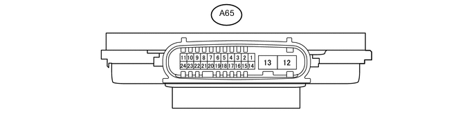
Disconnect the A65 headlight light control ECU sub-assembly RH connector.
-
Measure the resistance and voltage on the wire harness side connector according to the value(s) in the table below.
Terminal No. (Symbol) Wiring Color Terminal Description Condition Specified Condition A65-4 (IG) - Body ground G - Body ground Ignition power supply Engine switch off Below 1 V Engine switch on (IG) 11 to 14 V A65-12 (GND) - Body ground W-B - Body ground Ground Always Below 1 Ω -
Reconnect the A65 headlight light control ECU sub-assembly RH connector.
Tech Tips
Since the headlight light control ECU sub-assembly RH uses a waterproof connector, the voltage and pulses cannot be checked directly. The values listed are for reference only.
-
Measure the voltage and check of pulses according to the value(s) in the table below.
Terminal No. (Symbol) Wiring Color Terminal Description Condition Specified Condition A65-7(HLC) - Body ground R - Body ground Headlight cleaner motor operation signal Engine switch on (IG), when low beam headlights turn on, Headlight cleaner motor not operating 11 to 14 V Engine switch on (IG), when low beam headlights turn on, Headlight cleaner motor operating Below 1 V A65-8 (SW2) - Body ground LG - Body ground Headlight cleaner switch signal Engine switch on (IG), Headlight cleaner switch off 11 to 14 V Engine switch on (IG), Headlight cleaner switch on Below 1 V
-