BACK DOOR ADJUSTMENT
PROCEDURE
-
INSPECT BACK DOOR PANEL SUB-ASSEMBLY
-
Check that the clearance measurements of areas A to F are within the standard range.
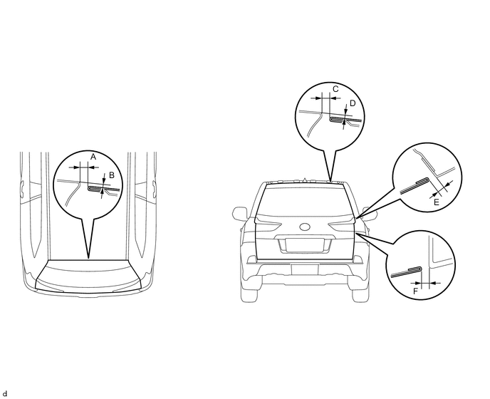
Standard Area Specified Condition Area Specified Condition A 5.3 to 8.3 mm (0.209 to 0.327 in.) D 1.1 to 4.1mm (0.0433 to 0.161 in.) B 1.5 to 4.5 mm (0.059 to 0.177 in.) E 3.6 to 6.6 mm (0.142 to 0.26 in.) C 5.4 to 6.6 mm (0.213 to 0.26 in.) F 3..35 to 6.35 mm (0.132 to 0.25 in.)
-
-
ADJUST REAR SWING GATE LOCK STRIKER
-
Check that the door fit and door linkages are adjusted correctly.
-
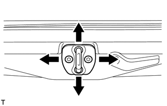
Using a T40 "TORX" socket, adjust the striker position by slightly loosening the striker mounting screws and hitting the striker with a plastic-faced hammer.
-
Using a T40 "TORX" socket, tighten the striker mounting screws after the adjustment.
- Torque:
- 23 N*m { 235 kgf*cm, 17 ft.*lbf }
-
-
ADJUST BACK DOOR PANEL SUB-ASSEMBLY
-
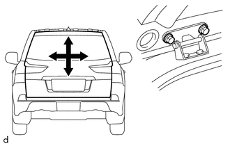
Loosen the hinge bolts.
-
Adjust the back door by moving it up and down and left and right so that the dimensions are within the specified range.
-
Tighten the hinge bolts.
- Torque:
- 19 N*m { 194 kgf*cm, 14 ft.*lbf }
-
Detach the seat belt anchor cover Click here.
-
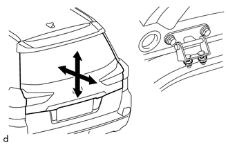
Loosen the hinge nuts.
-
Adjust the back door by moving it up and down and forward and backward so that the dimensions are within the specified range.
-
Tighten the hinge nuts.
- Torque:
- 19 N*m { 194 kgf*cm, 14 ft.*lbf }
-
Attach the seat belt anchor cover Click here.
-