BACK DOOR DISASSEMBLY
PROCEDURE
-
PRECAUTION
Note
After turning the engine switch off, waiting time may be required before disconnecting the cable from the battery terminal. Therefore, make sure to read the disconnecting the cable from the battery terminal notice before proceeding with work Click here.
-
REMOVE BACK DOOR GRIP
-
Using moulding remover A, detach the 5 claws and open the cover.
-
Using a T30 "TORX" socket wrench, remove the 2 "TORX" screws.
-
Detach the claw and remove the back door grip.
-
-
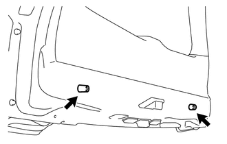
REMOVE LOWER BACK DOOR STOPPER CUSHION
-
Remove the 4 bolts and 2 lower back door stopper cushions.
-
-
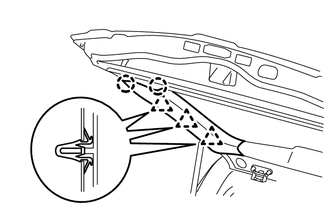
REMOVE CENTER BACK DOOR GARNISH
-
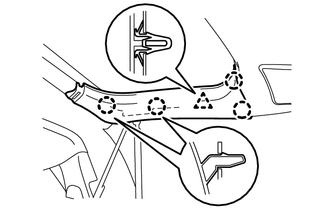
Detach the 5 clips and 4 claws, remove the center back door garnish.
-
Disconnect the connector.
-
-
REMOVE CENTER STOP LIGHT ASSEMBLY
-
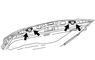
REMOVE BACK DOOR SIDE GARNISH LH
-
Detach the 3 clips and 2 claws and remove the back door side garnish LH.
-
-
REMOVE BACK DOOR SIDE GARNISH RH
Tech Tips
Use the same procedures described for the LH side.
-
w/ Power Back Door:
Detach the clip and 4 claws and remove the back door side garnish RH.
-
-
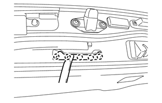
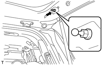
DISCONNECT POWER BACK DOOR ROD (w/ Power Back Door)
-
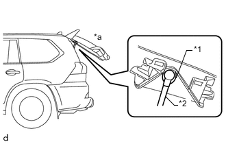
Text in Illustration *1 Power Back Door Rod *2 Hole of Back Door Service Hole Cover *a Back Door is Half-open Move the back door to a half-open position so that the hole in the center of the back door service hole cover is aligned lengthwise with the power back door rod.
-
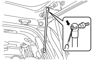
Using a thin-bladed screwdriver with its tip wrapped in protective tape, remove the stop ring from power back door rod as shown in the illustration.
Text in Illustration 
Protective Tape -
Detach the ball joint and disconnect the power back door rod.
-
-
REMOVE NO. 2 BACK DOOR SERVICE HOLE COVER (w/ Power Back Door)
-
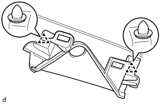
Detach the 2 clips and remove the No. 2 back door service hole cover.
-
-
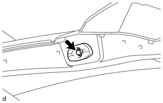
REMOVE BACK DOOR STAY BOLT (w/ Power Back Door)
-
Remove the back door stay bolt.
-
-
REMOVE BACK DOOR STAY PLATE (w/ Power Back Door)
-
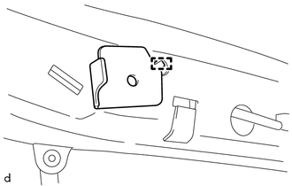
Detach the hook and back door stay plate.
-
-
REMOVE LIFT GATE WEATHERSTRIP
-
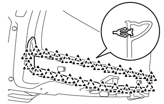
Detach the 25 clips and remove the lift gate weatherstrip.
Note
Do not pull strongly on the weatherstrip as it may be damage.
-
-
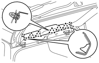
REMOVE BACK DOOR GARNISH
-
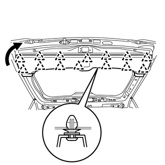
Using a clip remover, detach the 14 clips and remove the back door garnish as shown in the illustration.
-
-
REMOVE REAR HEADER SPEAKER ASSEMBLY (for 19 Speakers)
-
REMOVE POWER BACK DOOR SENSOR ASSEMBLY LH (w/ Power Back Door)
-
REMOVE POWER BACK DOOR SENSOR ASSEMBLY RH (w/ Power Back Door)
Tech Tips
Use the same procedures described for the LH side.
-
REMOVE REAR WIPER ARM AND BLADE ASSEMBLY
-
REMOVE REAR WIPER MOTOR GROMMET
-
REMOVE REAR WIPER MOTOR ASSEMBLY
-
REMOVE BACK DOOR LOCK COVER
-
REMOVE BACK DOOR LOCK ASSEMBLY (w/ Power Back Door)
-
REMOVE BACK DOOR LOCK ASSEMBLY (w/o Power Back Door)
-
REMOVE SWITCH BEZEL (w/ Power Back Door)
-
REMOVE DOOR CONTROL SWITCH (w/ Power Back Door)
-
REMOVE BACK DOOR OUTSIDE GARNISH SUB-ASSEMBLY
-
REMOVE BACK DOOR GARNISH RETAINER SUB-ASSEMBLY
-
REMOVE LICENSE PLATE LIGHT ASSEMBLY
-
REMOVE BACK DOOR OPENER SWITCH ASSEMBLY
-
REMOVE REAR TELEVISION CAMERA ASSEMBLY
-
REMOVE CUSHION
-
Remove the 2 cushions.
-
-
REMOVE LOWER BACK DOOR STOPPER
-
Remove the bolt and lower back door stopper.
-
-
REMOVE REAR SPOILER SUB-ASSEMBLY
Remove the rear spoiler sub-assembly Click here.
-
REMOVE REAR WASHER NOZZLE
-
REMOVE REAR LIGHT ASSEMBLY LH
-
REMOVE REAR LIGHT ASSEMBLY RH
Tech Tips
Use the same procedures described for the LH side.