OUTER REAR VIEW MIRROR DISASSEMBLY
CAUTION / NOTICE / HINT
Tech Tips
-
Use the same procedure for RHD and LHD vehicles.
-
The procedure listed below is for LHD vehicles.
-
Use the same procedure for the RH and LH sides.
-
The procedure listed below is for the LH side.
PROCEDURE
-
REMOVE OUTER MIRROR LH
-
REMOVE OUTER MIRROR COVER LH
-
REMOVE SIDE TURN SIGNAL LIGHT ASSEMBLY LH
-
REMOVE OUTER MIRROR RETRACTOR LH
-
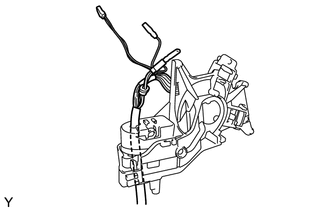
Remove the gasket
-
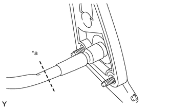
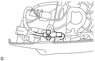
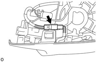
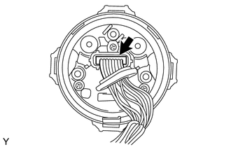
Text in Illustration *a Cut the wire harness here Cut the wire harness at the position shown in the illustration.
-
Remove the tape.
-
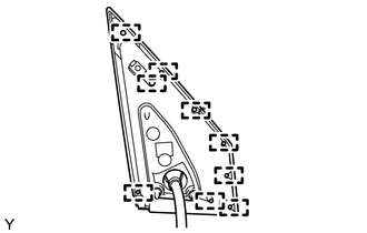
Detach the 9 guides and remove the gasket.
Note
Make sure to replace the gasket with a new one.
-
-
Remove the lower mirror cover
-
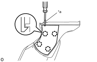
Text in Illustration *a Protective Tape Using a tin-blade screwdriver, detach the 4 claws and remove the lower mirror cover.
Tech Tips
Tape the tin-blade screwdriver tip before use.
Note
Make sure to replace the mirror cover lower with a new one.
-
-
Remove the base
-
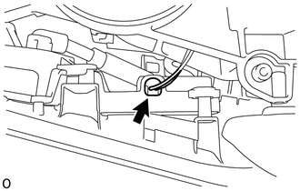
Remove the wire harness.
-
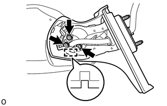
Using "TORX" socket wrench T25, remove the 3 "TORX" screws.
Note
Make sure to replace the "TORX" screws with new ones.
-
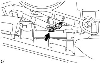
Detach the guide and remove the base.
-
-
Remove the body
-
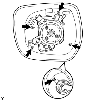
Remove the 5 screws and body.
-
-
Remove the body cover
-
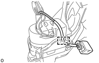
Open the outer mirror light connector cover.
-
Disconnect the outer mirror light connector.
-
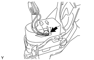
Detach the 2 claws and remove the connector from body cover.
-
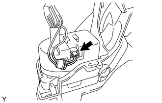
Disconnect the connector.
-
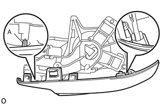
Detach the 2 guides and remove the body cover.
Note
Be careful not to break the guide shown in the part of the illustration labeled A.
-
-
Remove the actuator sub-assembly
-
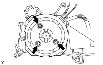
Remove the 3 screws.
-
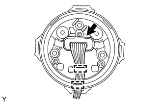
Detach the 2 clamps and open the cover.
-
Disconnect the connector and remove the actuator sub-assembly.
-
-
Remove the wire harness
-
Detach the clamp.
-
Open the cover.
-
Disconnect the connector.
-
Remove the wire harness.
-
-
Remove the support spring
-
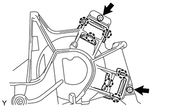
Remove the 2 screws.
-
Detach the 6 claws and remove the 2 support springs.
-
-
-
REMOVE SIDE TELEVISION CAMERA ASSEMBLY