POWER MIRROR CONTROL SYSTEM Front Passenger Side Power Mirror cannot be Adjusted with Power Mirror Switch
SYSTEM DESCRIPTION
The circuit detects the conditions of the multiplex network master switch assembly.
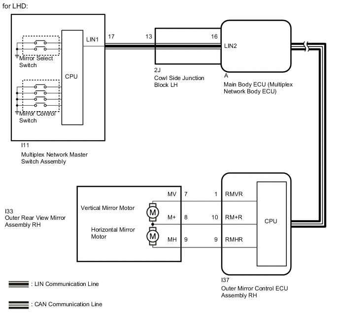
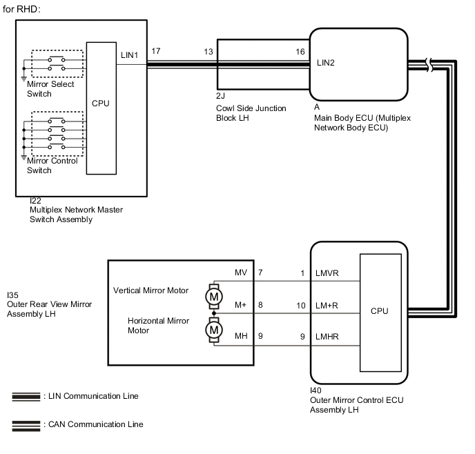
The multiplex network master switch assembly sends information about the operating condition of the mirror switch (switch input signals) through the CAN communication line. Then the switch input signals are sent to the outer mirror control ECU assembly RH*1 or LH*2. Mirror adjustment is controlled by the outer mirror control ECU assembly RH*1 or LH*2.
-
*1: for LHD
-
*2: for RHD
WIRING DIAGRAM
CAUTION / NOTICE / HINT
Note
-
The power mirror control system uses the CAN communication system and LIN communication system. Inspect the communication function by following How to Proceed with Troubleshooting. Troubleshoot the power mirror control system after confirming that the communication systems are functioning properly (See page ).
-
If the main body ECU (multiplex network body ECU) is replaced, refer to the Entry and Start System (for Entry Function) Click here.
PROCEDURE
-
READ VALUE USING GTS (OUTER MIRROR SWITCH)
-
Check the Data List for proper functioning of the mirror select switch and mirror control switch Click here.
Main Body Tester Display Measurement Item/Range Normal Condition Diagnostic Note Mirror Selection SW (R) Mirror select switch signal for RH mirror / ON or OFF ON: Switch in R position
OFF: Switch off or in L position
- Mirror Position SW (R) Mirror control switch signal (right) / ON or OFF ON: Right switch on
OFF: Any switch except right on or all switches off
- Mirror Position SW (L) Mirror control switch signal (left) / ON or OFF ON: Left switch on
OFF: Any switch except left on or all switches off
- Mirror Position SW (Up) Mirror control switch signal (up) / ON or OFF ON: Up switch on
OFF: Any switch except up on or all switches off
- Mirror Position SW (Dwn) Mirror control switch signal (down) / ON or OFF ON: Down switch on
OFF: Any switch except down on or all switches off
- OK On the GTS screen, each item changes between ON and OFF according to above chart.
NG 
CHECK MULTIPLEX NETWORK MASTER SWITCH ASSEMBLY Click here
OK 
-
-
INSPECT OUTER REAR VIEW MIRROR ASSEMBLY RH
-
for LHD
-
Remove the outer rear view mirror assembly RH Click here.
-
Inspect the outer rear view mirror assembly RH Click here.
-
-
for RHD
-
Remove the outer rear view mirror assembly LH Click here.
-
Inspect the outer rear view mirror assembly LH Click here.
Result Proceed to OK A NG (for LHD) B NG (for RHD) C -
B 
REPLACE OUTER REAR VIEW MIRROR ASSEMBLY RH Click here
C
REPLACE OUTER REAR VIEW MIRROR ASSEMBLY LH Click here
A
-
-
CHECK HARNESS AND CONNECTOR (OUTER MIRROR CONTROL ECU ASSEMBLY RH - OUTER REAR VIEW MIRROR ASSEMBLY RH)
-
for LHD
-
Disconnect the I37 outer mirror control ECU assembly RH connector.
-
Disconnect the I33 outer rear view mirror assembly RH connector.
-
Measure the resistance according to the value(s) in the table below.
Standard Resistance Tester Connection Condition Specified Condition I37-10 (RM+R) - I33-8 (M+) Always Below 1 Ω I37-9 (RMHR) - I33-9 (MH) Always Below 1 Ω I37-1 (RMVR) - I33-7 (MV) Always Below 1 Ω I37-10 (RM+R) or I33-8 (M+) - Body ground Always 10 kΩ or higher I37-9 (RMHR) or I33-9 (MH) - Body ground Always 10 kΩ or higher I37-1 (RMVR) or I33-7 (MV) - Body ground Always 10 kΩ or higher
-
-
for RHD
-
Disconnect the I40 outer mirror control ECU assembly LH connector.
-
Disconnect the I35 outer rear view mirror assembly LH connector.
-
Measure the resistance according to the value(s) in the table below.
Standard Resistance Tester Connection Condition Specified Condition I40-10 (LM+R) - I35-8 (M+) Always Below 1 Ω I40-9 (LMHR) - I35-9 (MH) Always Below 1 Ω I40-1 (LMVR) - I35-7 (MV) Always Below 1 Ω I40-10 (LM+R) or I35-8 (M+) - Body ground Always 10 kΩ or higher I40-9 (LMHR) or I35-9 (MH) - Body ground Always 10 kΩ or higher I40-1 (LMVR) or I35-7 (MV) - Body ground Always 10 kΩ or higher
Result Proceed to OK (for LHD) A OK (for RHD) B NG C -
A
REPLACE OUTER MIRROR CONTROL ECU ASSEMBLY RH Click here
B
REPLACE OUTER MIRROR CONTROL ECU ASSEMBLY LH Click here
C
REPAIR OR REPLACE HARNESS OR CONNECTOR
-
-
CHECK MULTIPLEX NETWORK MASTER SWITCH ASSEMBLY
-
Replace the multiplex network master switch assembly Click here.
-
Check the electrical remote control mirror function Click here.
OK Electrical remote control mirror function operates normally. Result Proceed to OK A NG (for LHD) B NG (for RHD) C
A
END (MULTIPLEX NETWORK MASTER SWITCH ASSEMBLY WAS DEFECTIVE)
B
REPLACE MAIN BODY ECU (MULTIPLEX NETWORK BODY ECU) Click here
C
REPLACE MAIN BODY ECU (MULTIPLEX NETWORK BODY ECU) Click here
-