POWER BACK DOOR SYSTEM TERMINALS OF ECU
-
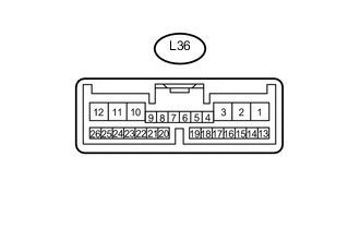
CHECK POWER BACK DOOR UNIT ASSEMBLY (POWER BACK DOOR ECU)
-
Disconnect the L36 power back door unit assembly (power back door ECU) connector.
-
Measure the voltage and resistance according to the value(s) in the table below.
Terminal No. (Symbol) Wiring Color Terminal Description Condition Specified Condition L36-10 (ECUB) - Body ground R - Body ground ECUB power supply Always 11 to 14 V L36-12 (B) - Body ground LA-B - Body ground Power supply Always 11 to 14 V L36-8 (IG) - Body ground G - Body ground IG power supply Engine switch on (IG) 11 to 14 V L36-8 (IG) - Body ground G - Body ground IG power supply Engine switch off Below 1 V L36-11 (GND) - Body ground W-B - Body ground Body ground Always Below 1 Ω If the result is not as specified, there may be a malfunction on the wire harness side.
-
Reconnect the L36 power back door unit assembly (power back door ECU) connector.
-
Measure the voltage and pulse according to the value(s) in the table below.
Terminal No. (Symbol) Wiring Color Terminal Description Condition Specified Condition L36-15 (OSL) - L36-14 (OSE) G - BE Power back door sensor LH circuit Power back door sensor LH not pressed 4 to 6 V L36-15 (OSL) - L36-14 (OSE) G - BE Power back door sensor LH circuit Power back door sensor LH pressed Below 1 V L36-13 (OSR) - L36-14 (OSE) P - BE Power back door sensor RH circuit Power back door sensor RH not pressed 4 to 6 V L36-13 (OSR) - L36-14 (OSE) P - BE Power back door sensor RH circuit Power back door sensor RH pressed Below 1 V L36-17 (MSW) - Body ground W - Body ground Power back door main switch signal circuit Power back door main switch not pushed (on) Below 1.5 V L36-17 (MSW) - Body ground W - Body ground Power back door main switch signal circuit Power back door main switch pushed (off) 6 V or higher L36-4 (DS1) - Body ground R - Body ground Back door control switch signal circuit Back door control switch on Below 1 Ω L36-4 (DS1) - Body ground R - Body ground Back door control switch signal circuit Back door control switch off Pulse generation L36-26 (BZR+) - Body ground L - Body ground Power back door warning buzzer signal input Power back door warning buzzer sounding Pulse generation L36-26 (BZR+) - Body ground L - Body ground Power back door warning buzzer signal input Power back door warning buzzer stopped Below 1 V L36-2 (DC+) - L36-1 (DC-) LA-R - LA-B Power back door lock motor circuit Power back door lock motor operating 11 to 14 V L36-2 (DC+) - L36-1 (DC-) LA-R - LA-B Power back door lock motor circuit Power back door lock motor stopped Below 1 V L36-17 (MSW) - Body ground W - Body ground Power back door main switch signal circuit Power back door main switch not pushed (on) Below 1 V L36-17 (MSW) - Body ground W - Body ground Power back door main switch signal circuit Power back door main switch pushed (off) Pulse generation L36-20 (FUL) - Body ground W - Body ground Back door courtesy switch signal circuit Back door opened Below 1 V L36-20 (FUL) - Body ground W - Body ground Back door courtesy switch signal circuit Back door closed Pulse generation L36-4 (DS1) - Body ground R - Body ground Back door control switch signal circuit Back door control switch on Below 1 V L36-4 (DS1) - Body ground R - Body ground Back door control switch signal circuit Back door control switch off Pulse generation L36-16 (PAWL) - Body ground B - Body ground Back door lock pawl switch signal circuit Back door fully open Below 1 V L36-16 (PAWL) - Body ground B - Body ground Back door lock pawl switch signal circuit Partially close 11 to 14 V L36-16 (PAWL) - Body ground B - Body ground Back door lock pawl switch signal circuit Back door fully close 11 to 14 V L36-16 (PAWL) - Body ground B - Body ground Back door lock pawl switch signal circuit Power back door operate stop Below 1 V L36-22 (HAF) - Body ground G - Body ground Back door lock half-latch switch signal circuit Back door opened Below 1 V L36-22 (HAF) - Body ground G - Body ground Back door lock half-latch switch signal circuit Back door closed Pulse generation L36-24 (POS) - Body ground B - Body ground Back door lock position switch signal circuit Back door closed Below 1 V L36-24 (POS) - Body ground B - Body ground Back door lock position switch signal circuit Back door opened Pulse generation L36-23 (CYLH) - Body ground G - Body ground Lower tail gate courtesy switch LH circuit Lower tail gate opened Below 1 V L36-23 (CYLH) - Body ground G - Body ground Lower tail gate courtesy switch LH circuit Lower tail gate closed Pulse generation L36-7 (CYRH) - Body ground P - Body ground Lower tail gate courtesy switch RH circuit Lower tail gates opened Below 1 V L36-7 (CYRH) - Body ground P - Body ground Lower tail gate courtesy switch RH circuit Lower tail gate closed Pulse generation
-
-
CHECK MAIN BODY ECU (MULTIPLEX NETWORK BODY ECU)
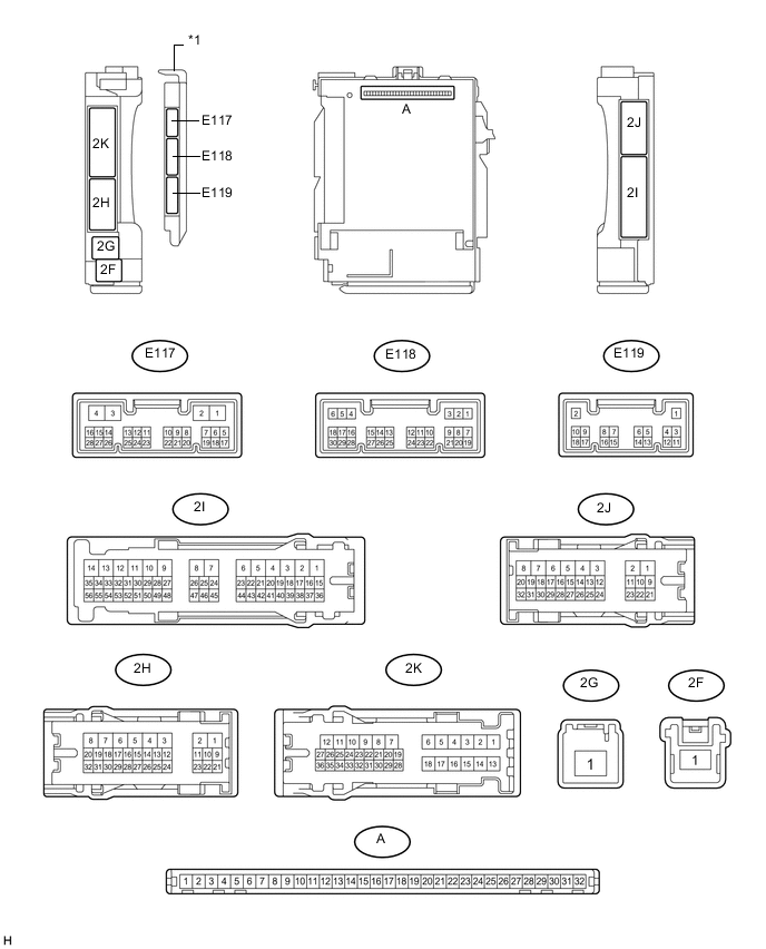
Text in Illustration *1 Main Body ECU (Multiplex Network Body ECU) - -
-
Remove the main body ECU (multiplex network body ECU) from the cowl side junction block LH.
-
Connect the cowl side junction block LH connectors.
-
Measure the voltage and resistance according to the value(s) in the table below.
Terminal No. (Symbol) Wiring Color Terminal Description Condition Specified Condition A-31 (BECU) - Body ground None - Body ground Battery power supply Always 11 to 14 V A-30 (ACC) - Body ground None - Body ground ACC power supply Engine switch on (ACC) 11 to 14 V A-11 (GND1) - Body ground None - Body ground Ground Always Below 1 Ω -
Install the main body ECU (multiplex network body ECU).
-
Measure the voltage according to the value(s) in the table below.
Terminal No. (Symbol) Wiring Color Terminal Description Condition Specified Condition E117-5 (PBDS) - Body ground B - Body ground Door control switch circuit Door control switch pushed (on) Below 1 V E117-5 (PBDS) - Body ground B - Body ground Door control switch circuit Door control switch not pushed (off) Pulse generation
-