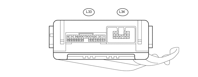
TAIL GATE CLOSER SYSTEM TERMINALS OF ECU
-
CHECK NO. 2 MAIN BODY ECU
-
Disconnect the L33 and L34 No. 2 main body ECU connectors.
-
Measure the voltage and resistance according to the value(s) in the table below.
Terminal No. (Symbol) Wiring Color Terminal Description Condition Specified Condition L33-14 (BECU) - Body ground R - Body ground BECU power supply Always 11 to 14 V L33-13 (SIG) - Body ground B - Body ground SIG power supply Engine switch on (IG) 11 to 14 V L33-13 (SIG) - Body ground B - Body ground SIG power supply Engine switch off Below 1 V L34-5 (B) - Body ground LA-B - Body ground Lower tail gate lock motor RH power supply Always 11 to 14 V L34-6 (B) - Body ground LA-W - Body ground Lower tail gate lock motor LH power supply Always 11 to 14 V L33-7 (GND) - Body ground W-B - Body ground Body ground Always Below 1 Ω L34-7 (GND) - Body ground W-B - Body ground Body ground Always Below 1 Ω L33-19 (BDSU) - Body ground V - Body ground Back door remote control signal circuit Back door remote control pulled (on) Below 1 Ω L33-19 (BDSU) - Body ground V - Body ground Back door remote control signal circuit Back door remote control free (off) 10 kΩ or higher If the result is not as specified, there may be a malfunction on the wire harness side.
-
Reconnect the L33 and L34 No. 2 main body ECU connectors.
-
Measure the voltage according to the value(s) in the table below.
Terminal No. (Symbol) Wiring Color Terminal Description Condition Specified Condition L34-3 (DC+) - L34-7 (GND) R - W-B Lower tail gate lock motor LH circuit Lower tail gate lock motor LH operating (close) 11 to 14 V L34-3 (DC+) - L34-7 (GND) R - W-B Lower tail gate lock motor LH circuit Lower tail gate lock motor LH stopped Below 1 V L34-8 (DC-) - L34-7 (GND) B - W-B Lower tail gate lock motor LH circuit Lower tail gate lock motor LH operating (open) 11 to 14 V L34-8 (DC-) - L34-7 (GND) B - W-B Lower tail gate lock motor LH circuit Lower tail gate lock motor LH stopped Below 1 V L34-2 (DC+) - L34-7 (GND) G - W-B Lower tail gate lock motor RH circuit Lower tail gate lock motor RH operating (close) 11 to 14 V L34-2 (DC+) - L34-7 (GND) G - W-B Lower tail gate lock motor RH circuit Lower tail gate lock motor RH stopped Below 1 V L34-1 (DC-) - L34-7 (GND) W - W-B Lower tail gate lock motor RH circuit Lower tail gate lock motor RH operating (open) 11 to 14 V L34-1 (DC-) - L34-7 (GND) W - W-B Lower tail gate lock motor RH circuit Lower tail gate lock motor RH stopped Below 1 V L34-9 (HAF) - L34-7 (GND) GR - W-B Half-latch switch LH signal circuit Lower tail gate open Below 1 V L34-9 (HAF) - L34-7 (GND) GR - W-B Half-latch switch LH signal circuit Lower tail gate closed Pulse generation
(See waveform 1)
L33-8 (HAF) - L34-7 (GND) B - W-B Half-latch switch RH signal circuit Lower tail gate open Below 1 V L33-8 (HAF) - L34-7 (GND) B - W-B Half-latch switch RH signal circuit Lower tail gate closed Pulse generation
(See waveform 1)
L34-4 (FUL) - L34-7 (GND) G - W-B Lower tail gate courtesy switch LH signal circuit Lower tail gate open Below 1 V L34-4 (FUL) - L34-7 (GND) G - W-B Lower tail gate courtesy switch LH signal circuit Lower tail gate closed Pulse generation
(See waveform 1)
L33-22 (FUL) - L34-7 (GND) P - W-B Lower tail gate courtesy switch RH signal circuit Lower tail gate open Below 1 V L33-22 (FUL) - L34-7 (GND) P - W-B Lower tail gate courtesy switch RH signal circuit Lower tail gate closed Pulse generation
(See waveform 1)
L34-10 (LMT) - L34-7 (GND) P - W-B Close position switch LH signal circuit Lower tail gate closed Below 1 V L34-10 (LMT) - L34-7 (GND) P - W-B Close position switch LH signal circuit Lower tail gate open Pulse generation
(See waveform 2)
L33-17 (LMT) - L34-7 (GND) L - W-B Close position switch RH signal circuit Lower tail gate closed Below 1 V L33-17 (LMT) - L34-7 (GND) L - W-B Close position switch RH signal circuit Lower tail gate open Pulse generation
(See waveform 2)
L33-15 (POL) - L34-7 (GND) L - W-B Pawl switch LH signal circuit Lower tail gate lock motor LH is operating Below 1 V L33-15 (POL) - L34-7 (GND) L - W-B Pawl switch LH signal circuit Lower tail gate open Pulse generation
(See waveform 2)
L33-16 (POL) - L34-7 (GND) R - W-B Pawl switch RH signal circuit Lower tail gate lock motor RH is operating Below 1 V L33-16 (POL) - L34-7 (GND) R - W-B Pawl switch RH signal circuit Lower tail gate open Pulse generation
(See waveform 2)
L33-19 (BDSU) - L34-7 (GND) V - W-B Back door remote control signal circuit Back door remote control pulled (on) Below 1 V L33-19 (BDSU) - L34-7 (GND) V - W-B Back door remote control signal circuit Back door remote control free (off) Pulse generation
(See waveform 3)
-
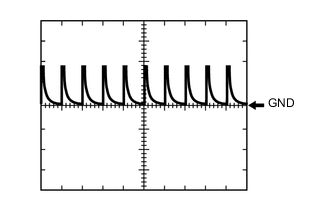
Using an oscilloscope, check waveform 1.
Waveform 1 (Reference) Item Content Terminal (Symbol)
-
L34-9 (HAF) - L34-7 (GND)
-
L33-8 (HAF) - L34-7 (GND)
-
L34-4 (FUL) - L34-7 (GND)
-
L33-22 (FUL) - L34-7 (GND)
Tool Setting 5 V/DIV., 5 ms/DIV Condition Lower tail gate closed -
-
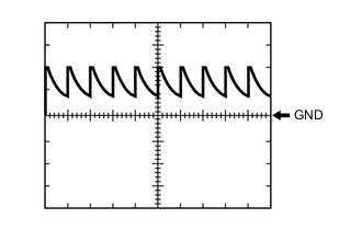
Using an oscilloscope, check waveform 2.
Waveform 2 (Reference) Item Content Terminal (Symbol)
-
L34-10 (LMT) - L34-7 (GND)
-
L33-17 (LMT) - L34-7 (GND)
-
L34-15 (POL) - L34-7 (GND)
-
L33-16 (POL) - L34-7 (GND)
Tool Setting 5 V/DIV., 5 ms/DIV Condition Lower tail gate open -
-
Using an oscilloscope, check waveform 3.
Waveform 3 (Reference) Item Content Terminal (Symbol) L33-19 (BDSU) - L34-7 (GND) Tool Setting 5 V/DIV., 5 ms/DIV Condition Back door remote control free (off)
-