SLIDING ROOF SYSTEM, Diagnostic DTC:B2342
| DTC Code | DTC Name |
|---|---|
| B2342 | Switch Failure |
DESCRIPTION
This DTC is stored when the sliding roof drive gear (sliding roof ECU) detects that the sliding roof switch in the map light is stuck for 30 seconds or more.
| DTC Code | DTC Detection Condition | Trouble Area |
|---|---|---|
| B2342 | The sliding roof drive gear (sliding roof ECU) detects that the sliding roof switch in the map light is stuck for 30 seconds or more. |
|
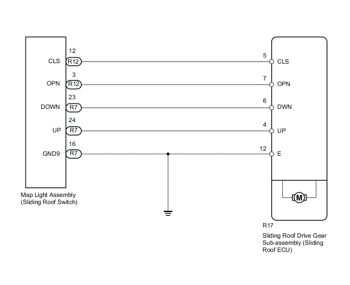
WIRING DIAGRAM
PROCEDURE
-
CHECK FOR DTC
-
Clear the DTCs Click here.
-
Check the DTCs Click here.
Result Result Proceed to DTC B2342 is output A No DTC is output B
B 
USE SIMULATION METHOD TO CHECK Click here
A 
-
-
READ VALUE USING INTELLIGENT TESTER (SWITCH STATUS)
-
Use the Data List to check if the sliding roof switch is functioning properly Click here.
Sliding Roof Tester Display Measurement Item/Range Normal Condition Diagnostic Note Open Switch Failure(Past) OPEN switch failure signal (Past)/ON or OFF ON: OPEN switch failure signal (Past)
OFF: No OPEN switch failure signal (Past)
- Close Switch Failure(Past) CLOSE switch failure signal (Past)/ON or OFF ON: CLOSE switch failure signal (Past)
OFF: No CLOSE switch failure signal (Past)
- Up Switch Failure(Past) UP switch failure signal (Past)/ON or OFF ON: UP switch failure signal (Past)
OFF: No UP switch failure signal (Past)
- Down Switch Failure(Past) DOWN switch failure signal (Past)/ON or OFF ON: DOWN switch failure signal (Past)
OFF: No DOWN switch failure signal (Past)
- Open Switch Failure(Current) OPEN switch failure signal (Current)/ON or OFF ON: OPEN switch failure signal (Current)
OFF: No OPEN switch failure signal (Current)
- Close Switch Failure(Current) CLOSE switch failure signal (Current)/ON or OFF ON: CLOSE switch failure signal (Current)
OFF: No CLOSE switch failure signal (Current)
- Up Switch Failure(Current) UP switch failure signal (Current)/ON or OFF ON: UP switch failure signal (Current)
OFF: No UP switch failure signal (Current)
- Down Switch Failure(Current) DOWN switch failure signal (Current)/ON or OFF ON: DOWN switch failure signal (Current)
OFF: No DOWN switch failure signal (Current)
- OK "OFF" appears on screen.
OK
REPLACE SLIDING ROOF DRIVE GEAR SUB-ASSEMBLY (SLIDING ROOF ECU) Click here
NG
-
-
INSPECT MAP LIGHT ASSEMBLY (SLIDING ROOF SWITCH)
-
Remove the map light assembly Click here.
-
Measure the resistance according to the value(s) in the table below.
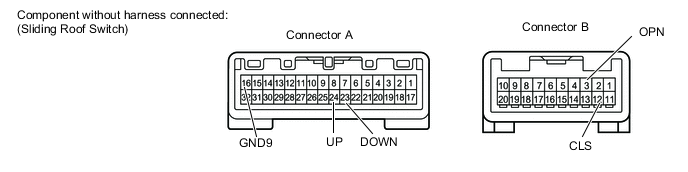
Standard Resistance Tester Connection Switch Condition Specified Condition A-24 (UP) - A-16 (GND9) UP switch is pressed Below 1 Ω A-24 (UP) - A-16 (GND9) UP switch is not pressed 10 kΩ or higher A-23 (DOWN) - A-16 (GND9) DOWN switch is pressed Below 1 Ω A-23 (DOWN) - A-16 (GND9) DOWN switch is not pressed 10 kΩ or higher B-3 (OPN) - A-16 (GND9) OPEN switch is pressed Below 1 Ω B-3 (OPN) - A-16 (GND9) OPEN switch is not pressed 10 kΩ or higher B-12 (CLS) - A-16 (GND9) CLOSE switch is pressed Below 1 Ω B-12 (CLS) - A-16 (GND9) CLOSE switch is not pressed 10 kΩ or higher
NG
REPLACE MAP LIGHT ASSEMBLY (SLIDING ROOF SWITCH) Click here
OK
-
-
CHECK HARNESS AND CONNECTOR (SLIDING ROOF DRIVE GEAR - MAP LIGHT)
-
Disconnect the R17 sliding roof drive gear sub-assembly (sliding roof ECU) connector.
-
Disconnect the R7 and R12 map light assembly connectors.
-
Measure the resistance according to the value(s) in the table below.
Standard Resistance Tester Connection Condition Specified Condition R17-4 (UP) - R7-24 (UP) Always Below 1 Ω R17-6 (DWN) - R7-23 (DOWN) Always Below 1 Ω R17-7 (OPN) - R12-3 (OPN) Always Below 1 Ω R17-5 (CLS) - R12-12 (CLS) Always Below 1 Ω R7-16 (GND9) - Body ground Always Below 1 Ω R17-12 (E) - Body ground Always Below 1 Ω R17-4 (UP) or R7-24 (UP) - Body ground Always 10 kΩ or higher R17-6 (DWN) or R7-23 (DOWN) - Body ground Always 10 kΩ or higher R17-7 (OPN) or R12-3 (OPN) - Body ground Always 10 kΩ or higher R17-9 (CLS) or R12-12 (CLS) - Body ground Always 10 kΩ or higher
OK
REPLACE SLIDING ROOF DRIVE GEAR SUB-ASSEMBLY (SLIDING ROOF ECU) Click here
NG
REPAIR OR REPLACE HARNESS OR CONNECTOR
-