ROOF HEADLINING REASSEMBLY
CAUTION / NOTICE / HINT
Tech Tips
-
Use the same procedure for RHD and LHD vehicles.
-
The procedure listed below is for LHD vehicles.
PROCEDURE
-
INSTALL ANTENNA CORD SUB-ASSEMBLY
-
INSTALL NO. 1 ROOF WIRE
-
Place double-sided tape along the center of the harness marking and washer marking.
Tech Tips
Make sure that the double-sided tape is not peeling off or misaligned.
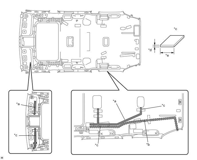
Text in Illustration *a Harness Marking *b Washer Marking *c Double-sided Tape *d 1 mm (0.0394 in.) *e 10 mm (0.394 in.) - - -
Remove the peeling paper from the double-sided tape while not touching the adhesive side.
-
Align the triangle mark of the No. 1 roof wire protector with the V mark of the headlining as shown in the illustration, and then attach the No. 1 roof wire protector.
-
Attach each clamp as shown in the illustration.
-
Align the No. 1 roof wire and washer hose with the V marks of the headlining as shown in the illustration, and attach them to the headlining.
Tech Tips
-
Attach the washer hose from the front to the point labeled A, and attach the washer hose from the rear to the point labeled B as shown in the illustration.
-
Attach the extra length of the washer hose to the part labeled C in the illustration.
-
-
Turn the visor connectors approximately 90° clockwise to install them to the roof headlining.
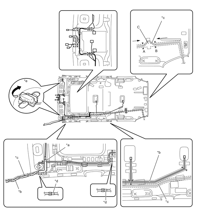
Text in Illustration *a Protector *b No. 1 Roof Wire *c Washer Hose *d Marking Tape *e Visor Connector - - -
Place tape at the wire harness marking and washer marking locations as shown in the illustration to fix the No. 1 roof wire and washer hose in place.
Tech Tips
Apply sufficient pressure when placing tape.
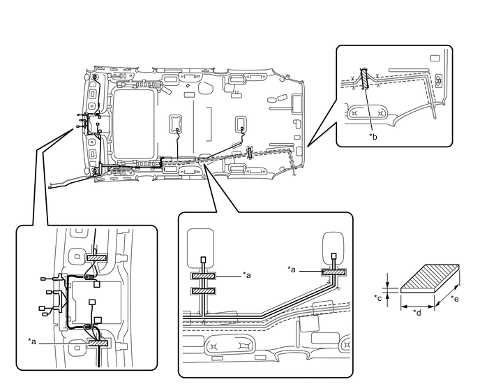
Text in Illustration *a Harness Marking *b Washer Marking *c 1 mm (0.0394 in.) *d 20 mm (0.787 in.) *e 100 mm (3.94 in.) - - 
Tape - -
-
-
INSTALL NO. 4 ROOF SILENCER PAD
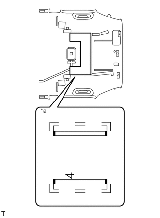
Text in Illustration *a Silencer Marking
-
Align the silencer marking on the roof headlining with the No. 4 roof silencer pad and install the No. 4 roof silencer pad using double-sided tape as shown in the illustration.
-
-
INSTALL NO. 1 ROOF SILENCER PAD
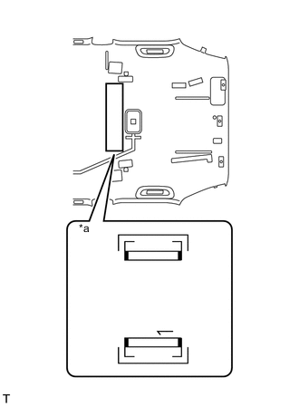
Text in Illustration *a Silencer Marking
-
Align the silencer marking on the roof headlining with the No. 1 roof silencer pad and install the No. 1 roof silencer pad using double-sided tape as shown in the illustration.
-
-
INSTALL NO. 2 AIR OUTLET GRILLE ASSEMBLY
Tech Tips
Use the same procedure for both No. 2 air outlet grille assemblies.
-
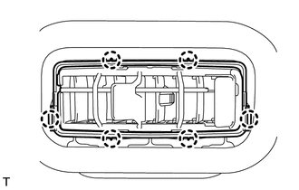
Attach the 6 claws to install the No. 2 air outlet grille assembly.
-
-
INSTALL NO. 1 AIR OUTLET GRILLE ASSEMBLY
Tech Tips
Use the same procedures described for the No. 2 air outlet grille assembly.