FRONT CONSOLE BOX(w/ Cool Box) INSPECTION
PROCEDURE
-
INSPECT COOLER CONTROL SWITCH SUB-ASSEMBLY
-
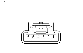
Text in Illustration *a Component without harness connected:
Cooler Control Switch Sub-assembly
Measure the resistance according to the value(s) in the table below.
Standard Resistance Tester Connection Switch Condition Specified Condition 1 - 2 On Below 1 Ω 1 - 2 Off 10 kΩ or higher -
Apply battery voltage to the cooler control switch sub-assembly connector and check that the indicator illuminates.
OK Measurement Condition Specified Condition Battery positive (+) → Terminal 3
Battery negative (-) → Terminal 4
Indicator illuminates If the result is not as specified, replace the cooler control switch sub-assembly.
-
-
INSPECT COOL BOX BLOWER WITH FAN MOTOR SUB-ASSEMBLY
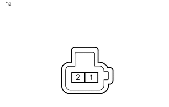
Text in Illustration *a Component without harness connected:
Cool Box Blower with Fan Motor Sub-assembly
-
Apply battery voltage to the blower motor connector and check the operation of the blower motor.
OK Measurement Condition Specified Condition Battery positive (+) → Terminal 1
Battery negative (-) → Terminal 2
Motor operates smoothly If the result is not as specified, replace the cool box blower with fan motor sub-assembly.
-
-
INSPECT NO. 3 COOLER THERMISTOR
-
Measure the resistance according to the value(s) in the table below.
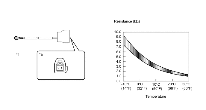
Standard Resistance Tester Connection Condition Specified Condition 1 - 2 -10°C (14°F) 7.40 to 9.20 kΩ 1 - 2 -5°C (23°F) 5.65 to 7.00 kΩ 1 - 2 0°C (32°F) 4.35 to 5.40 kΩ 1 - 2 5°C (41°F) 3.40 to 4.20 kΩ 1 - 2 10°C (50°F) 2.68 to 3.30 kΩ 1 - 2 15°C (59°F) 2.10 to 2.60 kΩ 1 - 2 20°C (68°F) 1.66 to 2.10 kΩ 1 - 2 25°C (77°F) 1.32 to 1.66 kΩ 1 - 2 30°C (86°F) 1.05 to 1.35 kΩ If the result is not as specified, replace the No. 3 cooler thermistor.
Note
-
Even slightly touching the sensor may change the resistance value. Be sure to hold the connector of the sensor.
-
When measuring, the sensor temperature must be the same as the ambient temperature.
Tech Tips
As the temperature increases, the resistance decreases (See the graph).
Text in Illustration *1 Sensor *a Component without harness connected:
No. 3 Cooler Thermistor
-
-