INSTRUMENT PANEL SAFETY PAD INSTALLATION
CAUTION / NOTICE / HINT
Tech Tips
-
Use the same procedure for RHD and LHD vehicles.
-
The procedure listed below is for LHD vehicles.
-
A bolt without a torque specification is shown in the standard bolt chart Click here.
PROCEDURE
-
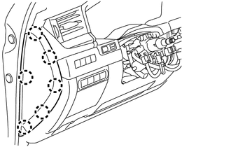
INSTALL INSTRUMENT PANEL SAFETY PAD ASSEMBLY
-
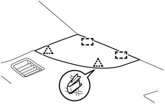
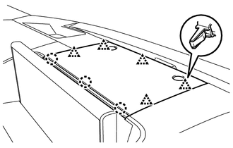
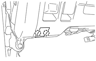
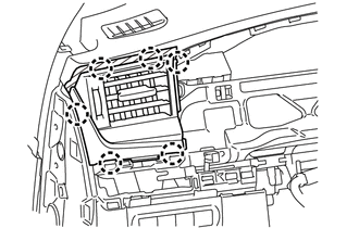
Cut off both ends at the positions shown in the illustration (runner) (when installing new part).
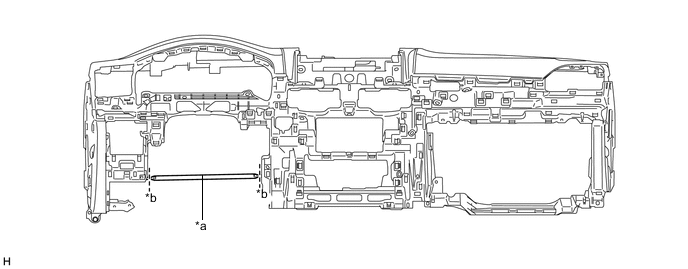
Text in Illustration *a Runner *b Cut-off Line -
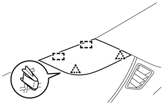
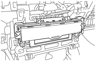
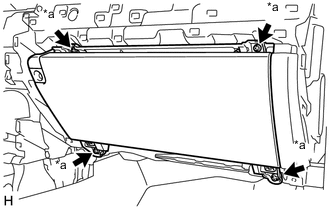
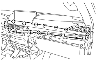
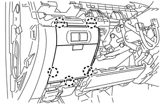
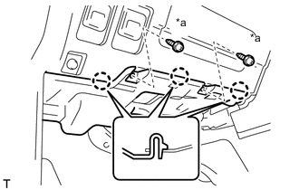
Install the instrument panel safety pad assembly with the 2 bolts <C>, 6 bolts <F> and 2nuts <G>.
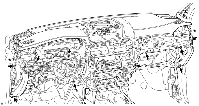
Text in Illustration *a Bolt <C> *b Bolt <F> *c Nut <G> - - -
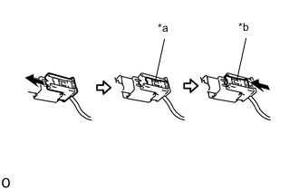
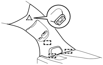
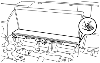
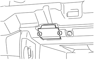
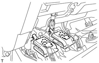
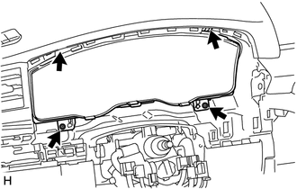
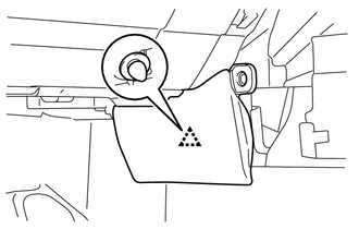
Text in Illustration *1 Lock Slider *a Lock Position Connect the passenger airbag connector.
Note
When handling the passenger airbag connector, take care not to damage the airbag wire harness.
-
Check that the lock slider is in the lock position.
-
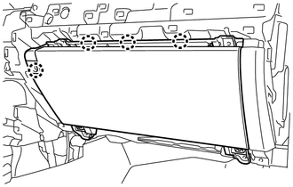
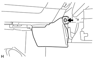
Install the 2 passenger airbag installation bolts <E>.
- Torque:
- 20 N*m { 204 kgf*cm, 15 ft.*lbf }
-
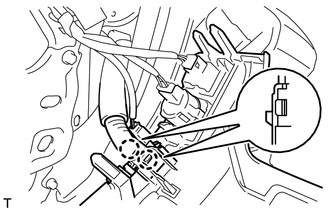
Connect the wire harness with the bolt.
-
Tighten the bolt and connect connector A.
Tech Tips
Tighten the bolt until it turns freely.
-
Connect the connectors and attach the clamps.
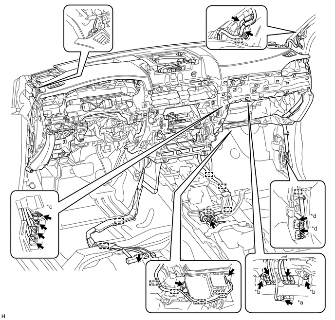
Text in Illustration *a Passenger Airbag Connector *b Passenger Airbag Installation Bolt <E> *c Bolt *d Connector A
-
-
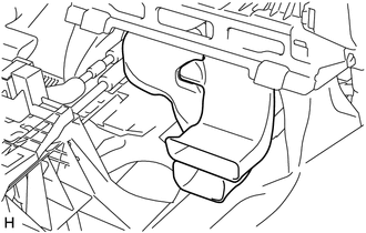
INSTALL NO. 2 COOLER AIR DUCT
-
Install the No. 2 cooler air duct.
-
-
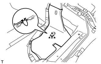
INSTALL REAR NO. 4 AIR DUCT
-
Attach the clip to install the rear No. 4 air duct.
-
-
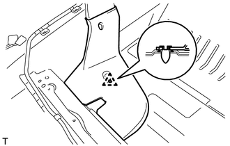
INSTALL REAR NO. 2 AIR DUCT
-
Attach the clip to install the rear No. 2 air duct.
-
-
INSTALL FRONT NO. 2 SPEAKER ASSEMBLY
Tech Tips
Use the same procedure for the RH and LH sides Click here.
-
INSTALL FRONT NO. 4 SPEAKER ASSEMBLY
-
INSTALL NO. 1 INSTRUMENT PANEL SPEAKER PANEL SUB-ASSEMBLY
-
Attach the 2 guides.
-
Attach the 2 clips to install the No. 1 instrument panel speaker panel sub-assembly.
-
-
INSTALL NO. 2 INSTRUMENT PANEL SPEAKER PANEL SUB-ASSEMBLY
-
Attach the 2 guides.
-
Attach the 2 clips to install the No. 2 instrument panel speaker panel sub-assembly.
-
-
INSTALL FRONT PILLAR GARNISH LH
-
Connect the connector.
-
Attach the clip and 3 guides to install the front pillar garnish LH.
-
-
INSTALL FRONT PILLAR GARNISH RH
Tech Tips
Use the same procedures described for the LH side.
-
INSTALL ASSIST GRIP SUB-ASSEMBLY
Tech Tips
Use the same procedure for both assist grip sub-assemblies.
-
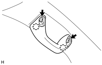
Attach the 2 claws to install the assist grip sub-assembly.
-
Install the 2 bolts.
-
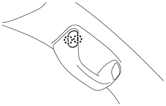
Attach the 2 claws to install the assist grip plug.
Tech Tips
Use the same procedure for all assist grip plugs.
-
-
INSTALL CENTER INSTRUMENT CLUSTER FINISH PANEL SUB-ASSEMBLY
-
Connect the connectors.
-
Attach the 6 claws to install the center instrument cluster finish panel sub-assembly.
-
-
INSTALL MULTI-MEDIA MODULE RECEIVER ASSEMBLY
-
INSTALL ACCESSORY METER ASSEMBLY
-
INSTALL NO. 1 SPEAKER OPENING COVER ASSEMBLY
-
Connect the connectors.
-
Attach the 5 clips and 3 claws to install the No. 1 speaker opening cover assembly.
-
-
INSTALL CENTER NO. 1 INSTRUMENT CLUSTER FINISH PANEL
-
Attach the 2 clips and claw to install the center No. 1 instrument cluster finish panel.
-
-
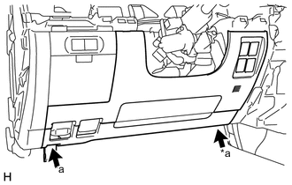
INSTALL LOWER NO. 2 INSTRUMENT PANEL FINISH PANEL
-
Connect the connector.
-
Attach the 4 claws to install the lower No. 2 instrument panel finish panel.
-
Text in Illustration *a Screw <D> Install the 4 screws <D>.
-
-
INSTALL INSTRUMENT PANEL BOX DOOR KNOB
Tech Tips
Use the same procedure for both instrument panel box door knobs.
-
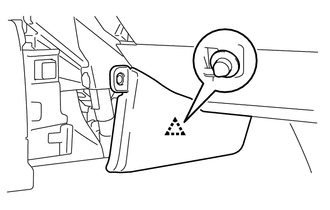
Attach the 2 claws to install the instrument panel box door knob.
-
-
INSTALL LOWER NO. 2 INSTRUMENT PANEL AIRBAG ASSEMBLY
-
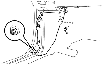
INSTALL COWL SIDE TRIM BOARD RH
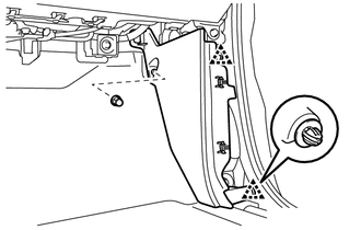
Text in Illustration *a Cap Nut
-
Attach the 2 clips to install the cowl side trim board RH.
-
Install the cap nut.
-
-
INSTALL FRONT DOOR SCUFF PLATE RH
-
INSTALL NO. 2 INSTRUMENT PANEL UNDER COVER SUB-ASSEMBLY
-
Connect the connector.
-
Attach the 4 claws to install the No. 2 instrument panel under cover sub-assembly.
-
-
INSTALL INSTRUMENT PANEL MOULDING SUB-ASSEMBLY
-
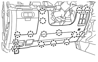
Connect the connectors.
-
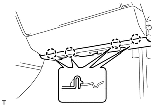
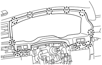
Attach the 20 claws to install the instrument panel moulding sub-assembly.
-
-
INSTALL INSTRUMENT SIDE PANEL RH
-
Attach the 6 claws to install the instrument side panel RH.
-
-
INSTALL INNER NO. 1 INSTRUMENT PANEL BRACKET COVER RH
-
Attach the clip to install the inner No. 1 instrument panel bracket cover RH.
-
Text in Illustration *a Clip <A> Install the clip <A>.
-
-
INSTALL LOWER NO. 1 INSTRUMENT PANEL AIRBAG ASSEMBLY
-
INSTALL INSTRUMENT PANEL BOX ASSEMBLY
-
Connect the connectors.
-
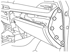
Attach the 5 claws to install the instrument panel box assembly.
-
-
INSTALL LOWER NO. 1 INSTRUMENT PANEL FINISH PANEL
-
Connect the connectors.
-
Attach the 2 claws to connect the 2 control cables.
-
Attach the 2 claws to install the sensor.
-
Attach the 15 claws to install the lower No. 1 instrument panel finish panel.
-
Text in Illustration *a Bolt <C> Install the 2 bolts <C>.
-
Attach the 2 claws to close the hole cover.
-
-
INSTALL COWL SIDE TRIM BOARD LH
Text in Illustration *a Cap Nut
-
Attach the 2 clips to install the cowl side trim board LH.
-
Install the cap nut.
-
-
INSTALL FRONT DOOR SCUFF PLATE LH
-
INSTALL NO. 1 INSTRUMENT PANEL UNDER COVER SUB-ASSEMBLY
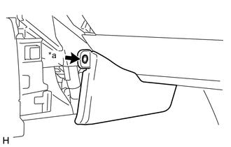
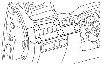
Text in Illustration *a Screw <B>
-
Connect the connectors.
-
Attach the 3 claws to install the No. 1 instrument panel under cover sub-assembly..
-
Install the 2 screws <B>.
-
-
INSTALL NO. 1 INSTRUMENT PANEL REGISTER ASSEMBLY
-
Connect the connector.
-
Attach the 6 claws to install the No. 1 instrument panel register assembly..
-
-
INSTALL COMBINATION METER ASSEMBLY
-
Connect the connectors.
-
Install the combination meter assembly with the 4 screws.
-
-
INSTALL NO. 2 INSTRUMENT CLUSTER FINISH PANEL SUB-ASSEMBLY
-
Connect the connectors.
-
Attach the 11 claws to install the No. 2 instrument cluster finish panel sub-assembly.
-
-
INSTALL NO. 1 SWITCH HOLE BASE
-
Connect the connectors.
-
Attach the 5 claws to install the No. 1 switch hole base.
-
-
INSTALL INSTRUMENT SIDE PANEL LH
-
Attach the 6 claws to install the instrument side panel LH.
-
-
INSTALL INNER NO. 1 INSTRUMENT PANEL BRACKET COVER LH
-
Attach the clip to install the inner No. 1 instrument panel bracket cover LH.
-
Text in Illustration *a Clip <A> Install the clip <A>.
-
-
INSTALL REAR CONSOLE BOX SUB-ASSEMBLY (w/o Cool Box)
-
INSTALL COOLING BOX ASSEMBLY (w/ Cool Box)
-
INSTALL HEADLIGHT DIMMER SWITCH ASSEMBLY
-
INSTALL FRONT SEAT ASSEMBLY LH
-
INSTALL FRONT SEAT ASSEMBLY RH
-
CONNECT CABLE TO NEGATIVE BATTERY TERMINAL
Note
When disconnecting the cable, some systems need to be initialized after the cable is reconnected Click here.
-
CHARGE REFRIGERANT (w/ Cool Box)
-
WARM UP ENGINE (w/ Cool Box)
-
CHECK FOR REFRIGERANT GAS LEAK
-
ENABLE AUTOAWAY/RETURN FUNCTION
-
Restore the autoaway/return function setting to the previous condition by changing the customize parameter Click here.
-
-
CHECK SRS WARNING LIGHT
-
INSTALL UPPER RADIATOR SUPPORT SEAL