WIRELESS CHARGING SYSTEM Status Signal Circuit
DESCRIPTION
This circuit sends a charging stop signal from the certification ECU (smart key ECU assembly) to the mobile wireless charger cradle assembly. Based on this signal, the wireless charging system stops the charging operation.
Tech Tips
The charging frequency of the wireless charging system overlaps with the electrical wave frequency band that is used when the entry and start system detects the position of the electrical key transmitter sub-assembly. Therefore, when the electrical key transmitter sub-assembly position is being detected, the charging stop signal from the certification ECU (smart key ECU assembly) makes the wireless charging system stop charging.
WIRING DIAGRAM
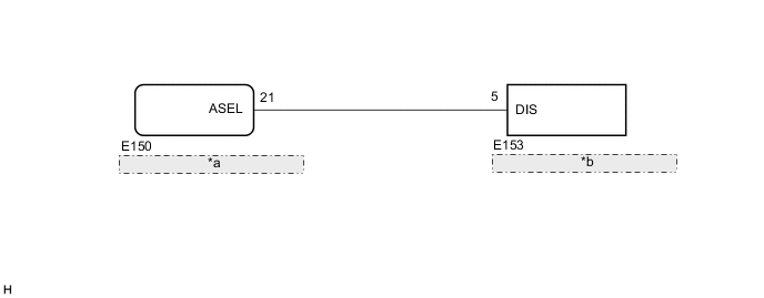
| *a | Certification ECU (Smart Key ECU Assembly) |
| *b | Mobile Wireless Charger Cradle Assembly |
CAUTION / NOTICE / HINT
Note
Before replacing the certification ECU (smart key ECU assembly), refer to the service bulletin.
PROCEDURE
-
CHECK MOBILE WIRELESS CHARGER CRADLE ASSEMBLY (DIS)
-
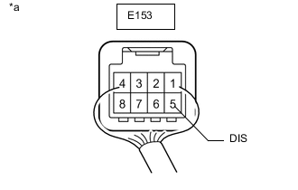
Text in Illustration *a Component with harness connected
(Mobile Wireless Charger Cradle Assembly)
Measure the voltage according to the value(s) in the table below.
Standard Voltage Tester Connection Condition Specified Condition E153-5 (DIS) - Body ground Within 1 second after turning power switch from off to on (ACC)*1 4.5 to 6.0 V When charging Below 1 V When charging is temporarily stopped by charging stop signal from certification ECU (smart key ECU assembly)*2 4.5 to 6.0 V *1: When the power switch is turned from off to on (ACC), the mobile wireless charger cradle assembly checks the charging stop signal for 1 second. If the charging stop signal is not 4 V or higher for 0.8 seconds or more within 1 second continuously, the mobile wireless charger cradle assembly determines that there is an open circuit in the charging stop signal circuit, blinkes the indicator amber (pattern 1), and stops operation until the next time the power switch is turned on (ACC). For the indicator blinking patterns, Click here
*2: For the certification ECU (smart key ECU assembly) charging stop signal reception conditions, Click here
Tech Tips
Check with the certification ECU (smart key ECU assembly) connector connected.
OK 
PROCEED TO NEXT SUSPECTED AREA SHOWN IN PROBLEM SYMPTOMS TABLE Click here
NG 
-
-
CHECK HARNESS AND CONNECTOR (MOBILE WIRELESS CHARGER CRADLE ASSEMBLY - CERTIFICATION ECU [SMART KEY ECU ASSEMBLY])
-
Disconnect the K1 mobile wireless charger cradle assembly connector.
-
Disconnect the I52 certification ECU (smart key ECU assembly) connector.
-
Measure the resistance according to the value(s) in the table below.
Standard Resistance Tester Connection Condition Specified Condition E153-5 (DIS) - E150-21 (ASEL) Always Below 1 Ω E153-5 (DIS) or E150-21 (ASEL) - Body ground Always 10 kΩ or higher
OK
REPLACE CERTIFICATION ECU (SMART KEY ECU ASSEMBLY)
NG
REPAIR OR REPLACE HARNESS AND CONNECTOR
-