POWER WINDOW CONTROL SYSTEM TERMINALS OF ECU
-
CHECK FRONT POWER WINDOW REGULATOR MOTOR ASSEMBLY LH

-
Disconnect the I12 motor connector.
-
Measure the resistance and voltage according to the value(s) in the table below.
Terminal No. (Symbol) Wiring Color Terminal Description Condition Specified Condition I12-2 (B) - I12-1 (GND) L - W-B Battery power supply Always 11 to 14 V I12-1 (GND) - Body ground W-B - Body ground Ground Always Below 1 Ω If the result is not as specified, there may be a malfunction on the wire harness side.
-
Reconnect the I12 motor connector.
-
Measure the voltage according to the value(s) in the table below.
Terminal No. (Symbol) Wiring Color Terminal Description Condition Specified Condition I12-10 (UP) - I12-1 (GND) L - W-B Power window up operation Engine switch on (IG), multiplex network master switch off → up 11 to 14 V → Below 1 V I12-10 (UP) - I12-1 (GND) L - W-B Power window up operation Engine switch on (IG), door glass fully open → power window auto up operation → door glass fully closed 11 to 14 V → Below 1 V → 11 to 14 V I12-7 (DOWN) - I12-1 (GND) B - W-B Power window down operation Engine switch on (IG), multiplex network master switch off → down 11 to 14 V → Below 1 V I12-7 (DOWN) - I12-1 (GND) B - W-B Power window down operation Engine switch on (IG), door glass fully closed → power window auto down operation → door glass fully open 11 to 14 V → Below 1 V → 11 to 14 V If the result is not as specified, the motor may be malfunctioning.
-
-
CHECK FRONT POWER WINDOW REGULATOR MOTOR RH

-
Disconnect the I4 motor connector.
-
Measure the resistance and voltage according to the value(s) in the table below.
Terminal No. (Symbol) Wiring Color Terminal Description Condition Specified Condition I4-2 (B) - I4-1 (GND) L - W-B Battery power supply Always 11 to 14 V I4-1 (GND) - Body ground W-B - Body ground Ground Always Below 1 Ω If the result is not as specified, there may be a malfunction on the wire harness side.
-
Reconnect the I4 motor connector.
-
Measure the voltage according to the value(s) in the table below.
Terminal No. (Symbol) Wiring Color Terminal Description Condition Specified Condition I4-10 (UP) - I4-1 (GND) L - W-B Power window up operation Engine switch on (IG), power window regulator switch off → up 11 to 14 V → Below 1 V I4-10 (UP) - I4-1 (GND) L - W-B Power window up operation Engine switch on (IG), door glass fully open → power window auto up operation → door glass fully closed 11 to 14 V → Below 1 V → 11 to 14 V I4-7 (DOWN) - I4-1 (GND) B - W-B Power window down operation Engine switch on (IG), power window regulator switch off → down 11 to 14 V → Below 1 V I4-7 (DOWN) - I4-1 (GND) B - W-B Power window down operation Engine switch on (IG), door glass fully closed → power window auto down operation → door glass fully open 11 to 14 V → Below 1 V → 11 to 14 V If the result is not as specified, the motor may be malfunctioning.
-
-
CHECK REAR POWER WINDOW REGULATOR MOTOR LH

-
Disconnect the J11 motor connector.
-
Measure the resistance and voltage according to the value(s) in the table below.
Terminal No. (Symbol) Wiring Color Terminal Description Condition Specified Condition J11-2 (B) - J11-1 (GND) L - W-B Battery power supply Always 11 to 14 V J11-1 (GND) - Body ground W-B - Body ground Ground Always Below 1 Ω If the result is not as specified, there may be a malfunction on the wire harness side.
-
Reconnect the J11 motor connector.
-
Measure the voltage according to the value(s) in the table below.
Terminal No. (Symbol) Wiring Color Terminal Description Condition Specified Condition J11-10 (UP) - J11-1 (GND) L - W-B Power window up operation Engine switch on (IG), power window regulator switch off → up 11 to 14 V → Below 1 V J11-10 (UP) - J11-1 (GND) L - W-B Power window up operation Engine switch on (IG), door glass fully open → power window auto up operation → door glass fully closed 11 to 14 V → Below 1 V → 11 to 14 V J11-7 (DOWN) - J11-1 (GND) B - W-B Power window down operation Engine switch on (IG), power window regulator switch off → down 11 to 14 V → Below 1 V J11-7 (DOWN) - J11-1 (GND) B - W-B Power window down operation Engine switch on (IG), door glass fully closed → power window auto down operation → door glass fully open 11 to 14 V → Below 1 V → 11 to 14 V If the result is not as specified, the motor may be malfunctioning.
-
-
CHECK REAR POWER WINDOW REGULATOR MOTOR RH

-
Disconnect the J4 motor connector.
-
Measure the resistance and voltage according to the value(s) in the table below.
Terminal No. (Symbol) Wiring Color Terminal Description Condition Specified Condition J4-2 (B) - J4-1 (GND) L - W-B Battery power supply Always 11 to 14 V J4-1 (GND) - Body ground W-B - Body ground Ground Always Below 1 Ω If the result is not as specified, there may be a malfunction on the wire harness side.
-
Reconnect the J4 motor connector.
-
Measure the voltage according to the value(s) in the table below.
Terminal No. (Symbol) Wiring Color Terminal Description Condition Specified Condition J4-10 (UP) - J4-1 (GND) L - W-B Power window up operation Engine switch on (IG), power window regulator switch off → up 11 to 14 V → Below 1 V J4-10 (UP) - J4-1 (GND) L - W-B Power window up operation Engine switch on (IG), door glass fully open → power window auto up operation → door glass fully closed 11 to 14 V → Below 1 V → 11 to 14 V J4-7 (DOWN) - J4-1 (GND) B - W-B Power window down operation Engine switch on (IG), power window regulator switch off → down 11 to 14 V → Below 1 V J4-7 (DOWN) - J4-1 (GND) B - W-B Power window down operation Engine switch on (IG), door glass fully closed → power window auto down operation → door glass fully open 11 to 14 V → Below 1 V → 11 to 14 V If the result is not as specified, the motor may be malfunctioning.
-
-
CHECK MULTIPLEX NETWORK MASTER SWITCH

-
Disconnect the I11*1 or I22*2 master switch connector.
-
Measure the resistance and voltage according to the value(s) in the table below.
for LHD Terminal No. (Symbol) Wiring Color Terminal Description Condition Specified Condition I11-11 (B) - I11-12 (GND) R - W-B Battery power supply Always 11 to 14 V I11-12 (GND) - Body ground W-B - Body ground Ground Always Below 1 Ω for RHD Terminal No. (Symbol) Wiring Color Terminal Description Condition Specified Condition I22-11 (B) - I22-12 (GND) R - W-B Battery power supply Always 11 to 14 V I22-12 (GND) - Body ground W-B - Body ground Ground Always Below 1 Ω If the result is not as specified, there may be a malfunction on the wire harness side.
-
Reconnect the I11*1 or I22*2 master switch connector.
-
Measure the voltage according to the value(s) in the table below.
for LHD Terminal No. (Symbol) Wiring Color Terminal Description Condition Specified Condition I11-20 (UP) - I11-12 (GND) L - W-B Power window up operation Engine switch on (IG), driver door power window regulator switch not pushed or pulled 11 to 14 V I11-20 (UP) - I11-12 (GND) L - W-B Power window up operation Engine switch on (IG), driver door power window moving, driver door power window regulator switch pulled halfway up (Manual operation) Below 1 V I11-15 (DOWN) - I11-12 (GND) B - W-B Power window down operation Engine switch on (IG), driver door power window regulator switch not pushed or pulled 11 to 14 V I11-15 (DOWN) - I11-12 (GND) B - W-B Power window down operation Engine switch on (IG), driver door power window moving, driver door power window regulator switch pushed halfway down (Manual operation) Below 1 V for RHD Terminal No. (Symbol) Wiring Color Terminal Description Condition Specified Condition I22-20 (UP) - I22-12 (GND) L - W-B Power window up operation Engine switch on (IG), driver door power window regulator switch not pushed or pulled 11 to 14 V I22-20 (UP) - I22-12 (GND) L - W-B Power window up operation Engine switch on (IG), driver door power window moving, driver door power window regulator switch pulled halfway up (Manual operation) Below 1 V I22-15 (DOWN) - I22-12 (GND) B - W-B Power window down operation Engine switch on (IG), driver door power window regulator switch not pushed or pulled 11 to 14 V I22-15 (DOWN) - I22-12 (GND) B - W-B Power window down operation Engine switch on (IG), driver door power window moving, driver door power window regulator switch pushed halfway down (Manual operation) Below 1 V If the result is not as specified, the master switch may be malfunctioning.
-
-
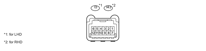
CHECK FRONT PASSENGER SIDE POWER WINDOW REGULATOR SWITCH
-
Disconnect the I3*1 or I43*2 switch connector.
-
Measure the resistance according to the value(s) in the table below.
for LHD Terminal No. (Symbol) Wiring Color Terminal Description Condition Specified Condition I3-5 (GND) - Body ground W-B - Body ground Ground Always Below 1 Ω for RHD Terminal No. (Symbol) Wiring Color Terminal Description Condition Specified Condition I43-5 (GND) - Body ground W-B - Body ground Ground Always Below 1 Ω If the result is not as specified, there may be a malfunction on the wire harness side.
-
Reconnect the I3*1 or I43*2 switch connector.
-
Measure the voltage according to the value(s) in the table below.
for LHD Terminal No. (Symbol) Wiring Color Terminal Description Condition Specified Condition I3-2 (UP) - I3-5 (GND) L - W-B Power window up operation Engine switch on (IG), power window regulator switch off → up 11 to 14 V → Below 1 V I3-10 (DOWN) - I3-5 (GND) B - W-B Power window down operation Engine switch on (IG), power window regulator switch off → down 11 to 14 V → Below 1 V I3-4 (AUTO) - I3-5 (GND) R - W-B Power window up operation Engine switch on (IG)and door glass fully open → power window auto up operation → door glass fully closed 11 to 14 V → Below 1 V → 11 to 14 V I3-4 (AUTO) - I3-5 (GND) R - W-B Power window down operation Engine switch on (IG), door glass fully closed → power window auto down operation → door glass fully open 11 to 14 V → Below 1 V → 11 to 14 V for RHD Terminal No. (Symbol) Wiring Color Terminal Description Condition Specified Condition I43-2 (UP) - I43-5 (GND) L - W-B Power window up operation Engine switch on (IG), power window regulator switch off → up 11 to 14 V → Below 1 V I43-10 (DOWN) - I43-5 (GND) B - W-B Power window down operation Engine switch on (IG), power window regulator switch off → down 11 to 14 V → Below 1 V I43-4 (AUTO) - I43-5 (GND) R - W-B Power window up operation Engine switch on (IG)and door glass fully open → power window auto up operation → door glass fully closed 11 to 14 V → Below 1 V → 11 to 14 V I43-4 (AUTO) - I43-5 (GND) R - W-B Power window down operation Engine switch on (IG), door glass fully closed → power window auto down operation → door glass fully open 11 to 14 V → Below 1 V → 11 to 14 V If the result is not as specified, the switch may be malfunctioning.
-
-
CHECK REAR POWER WINDOW REGULATOR SWITCH LH

-
Disconnect the J20 switch connector.
-
Measure the resistance according to the value(s) in the table below.
Terminal No. (Symbol) Wiring Color Terminal Description Condition Specified Condition J20-5 (GND) - Body ground W-B - Body ground Ground Always Below 1 Ω If the result is not as specified, there may be a malfunction on the wire harness side.
-
Reconnect the J20 switch connector.
-
Measure the voltage according to the value(s) in the table below.
Terminal No. (Symbol) Wiring Color Terminal Description Condition Specified Condition J20-2 (UP) - J20-5 (GND) L - W-B Power window up operation Engine switch on (IG), power window regulator switch off → up 11 to 14 V → Below 1 V J20-10 (DOWN) - J20-5 (GND) B - W-B Power window down operation Engine switch on (IG), power window regulator switch off → down 11 to 14 V → Below 1 V J20-4 (AUTO) - J20-5 (GND) R - W-B Power window up operation Engine switch on (IG), door glass fully open → power window auto up operation → door glass fully closed 11 to 14 V → Below 1 V → 11 to 14 V J20-4 (AUTO) - J20-5 (GND) R - W-B Power window down operation Engine switch on (IG), door glass fully closed → power window auto down operation → door glass fully open 11 to 14 V → Below 1 V → 11 to 14 V If the result is not as specified, the switch may be malfunctioning.
-
-
CHECK REAR POWER WINDOW REGULATOR SWITCH RH

-
Disconnect the J19 switch connector.
-
Measure the resistance according to the value(s) in the table below.
Terminal No. (Symbol) Wiring Color Terminal Description Condition Specified Condition J19-5 (GND) - Body ground W-B - Body ground Ground Always Below 1 Ω If the result is not as specified, there may be a malfunction on the wire harness side.
-
Reconnect the J19 switch connector.
-
Measure the voltage according to the value(s) in the table below.
Terminal No. (Symbol) Wiring Color Terminal Description Condition Specified Condition J19-2 (UP) - J19-5 (GND) L - W-B Power window up operation Engine switch on (IG), power window regulator switch off → up 11 to 14 V → Below 1 V J19-10 (DOWN) - J19-5 (GND) B - W-B Power window down operation Engine switch on (IG), power window regulator switch off → down 11 to 14 V → Below 1 V J19-4 (AUTO) - J19-5 (GND) R - W-B Power window up operation Engine switch on (IG), door glass fully open → power window auto up operation → door glass fully closed 11 to 14 V → Below 1 V → 11 to 14 V J19-4 (AUTO) - J19-5 (GND) R - W-B Power window down operation Engine switch on (IG), door glass fully closed → power window auto down operation → door glass fully open 11 to 14 V → Below 1 V → 11 to 14 V If the result is not as specified, the switch may be malfunctioning.
-
-
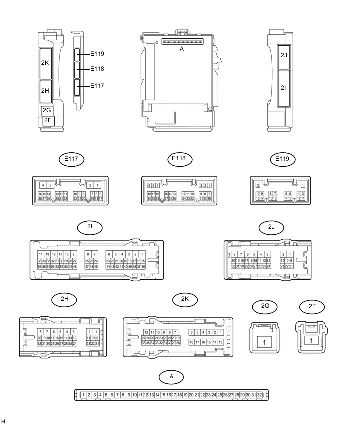
CHECK MAIN BODY ECU (COWL SIDE JUNCTION BLOCK LH)
-
Remove the main body ECU (multiplex network body ECU) from the cowl side junction block LH Click here
-
Measure the resistance and voltage according to value(s) in the table below.
Terminal No. (Symbol) Wiring Color Terminal Description Condition Specified Condition A-11 (GND1) - Body ground None - Body ground Ground Always Below 1 Ω A-31 (BECU) - Body ground None - Body ground Ground Always Below 1 Ω E118-6 (FLCY) - Body ground V - Body ground Driver side door courtesy light switch input*1
Front passenger side door courtesy light switch input*2
Driver side door open*1
Front passenger side door open*2
Below 1 Ω Driver side door closed*1
Front passenger side door closed*2
10 kΩ or higher E118-27 (FRCY) - Body ground V - Body ground Driver side door courtesy light switch input*2
Front passenger side door courtesy light switch input*21
Driver side door open*2
Front passenger side door open*1
Below 1 Ω Driver side door closed*2
Front passenger side door closed*1
10 kΩ or higher E118-29 (L2) - Body ground G - Body ground Driver door key-linked lock input Driver door key cylinder turned to lock Below 1 V Driver door key cylinder off Pulse generation E118-2 (UL3) - Body ground P - Body ground Driver door key-linked unlock input Driver door key cylinder turned to unlock Below 1 V Driver door key cylinder off Pulse generationr Tech Tips
-
*1: for LHD
-
*2: for RHD
-
If the result is not as specified, the wire harness side may have a malfunction.
-
-