SMOG VENTILATION SENSOR INSPECTION
PROCEDURE
-
INSPECT COOLER THERMISTOR (SMOG VENTILATION SENSOR)
-
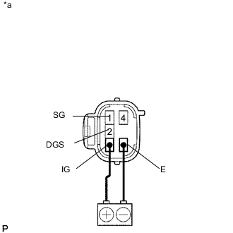
Text in Illustration *a Component without harness connected
Cooler Thermistor (Smog Ventilation Sensor)
HC, CO
-
Apply battery voltage to terminals 3 (IG) and 6 (E).
-
Allow exhaust gas (HC, CO) to travel to the sensing portion of the cooler thermistor (smog ventilation sensor), and measure the resistance between terminals 1 (SG) and 2 (DGS).
OK When the sensor is exposed to the exhaust gas, the resistance decreases. Tech Tips
The resistance before blowing exhaust gas is 15 to 40 kΩ.
If the resistance is not as specified, replace the cooler thermistor (smog ventilation sensor).
-
-
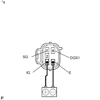
Text in Illustration *a Component without harness connected
Cooler Thermistor (Smog Ventilation Sensor)
NOx
-
Apply battery voltage to terminals 3 (IG) and 6 (E).
-
Allow exhaust gas (NOx) to travel to the sensing portion of the cooler thermistor (smog ventilation sensor), and measure the resistance between terminals 1 (SG) and 4 (DGS1).
OK When the sensor is exposed to the exhaust gas, the resistance increases. Tech Tips
The resistance before blowing exhaust gas is 2.5 to 40 kΩ.
If the resistance is not as specified, replace the cooler thermistor (smog ventilation sensor).
-
-