COMPRESSOR(for 3UR-FE) INSTALLATION

CAUTION / NOTICE / HINT
Tech Tips
A bolt without a torque specification is shown in the standard bolt chart Click here.
PROCEDURE
-
ADJUST COMPRESSOR OIL
-
When replacing the compressor and magnetic clutch with a new one, gradually discharge the refrigerant gas from the service valve, and drain the following amount of oil from the new compressor and magnetic clutch before installation.
Standard Condenser Size 22mm (0.8661 in.) (Oil capacity inside the new compressor and magnetic clutch: 140 + 15 cc (4.7 + 0.51 fl.oz.)) - (Remaining oil amount in the removed compressor and magnetic clutch) = (Oil amount to be removed from the new compressor when replacing) Condenser Size 16mm (0.6299 in.) (Oil capacity inside the new compressor and magnetic clutch: 135 + 15 cc (4.6 + 0.51 fl.oz.)) - (Remaining oil amount in the removed compressor and magnetic clutch) = (Oil amount to be removed from the new compressor when replacing) Note
-
When checking the compressor oil level, follow the A/C system precautions.
-
If a new compressor and magnetic clutch is installed without removing some oil remaining in the pipes of the vehicle, the oil amount will be too large. This prevents heat exchange in the refrigerant cycle and causes refrigerant failure.
-
If the volume of oil remaining in the removed compressor and magnetic clutch is too small, check for oil leakage.
-
Be sure to use ND-OIL 8 or equivalent compressor oil.
-
-
-
INSTALL COOLER COMPRESSOR ASSEMBLY
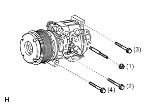
-
Install the cooler compressor assembly and stud bolt.
- Torque:
- 10 N*m { 102 kgf*cm, 7 ft.*lbf }
-
Install the 3 bolts and nut.
- Torque:
- 24.5 N*m { 250 kgf*cm, 18 ft.*lbf }
Tech Tips
Tighten the bolts and nut in the order shown in the illustration.
-
Connect the connector.
-
-
CONNECT NO. 1 COOLER REFRIGERANT DISCHARGE HOSE
-
Remove the attached vinyl tape from the No. 1 cooler refrigerant discharge hose.
-
Sufficiently apply compressor oil to a new O-ring and the fitting surface of the cooler compressor assembly.
Compressor oil ND-OIL 8 or equivalent -
Install the O-ring to the No. 1 cooler refrigerant discharge hose.
-
Connect the No. 1 cooler refrigerant discharge hose to the cooler compressor with the bolt.
- Torque:
- 9.8 N*m { 100 kgf*cm, 87 in.*lbf }
-
-
CONNECT SUCTION HOSE SUB-ASSEMBLY
-
Remove the attached vinyl tape from the suction hose sub-assembly.
-
Sufficiently apply compressor oil to a new O-ring and the fitting surface of the cooler compressor assembly.
Compressor oil ND-OIL 8 or equivalent -
Install the O-ring to the suction hose sub-assembly.
-
Connect the suction hose sub-assembly to the cooler compressor with the bolt.
- Torque:
- 9.8 N*m { 100 kgf*cm, 87 in.*lbf }
-
-
CONNECT NO. 2 ENGINE WIRE
-
Connect the No. 2 engine wire with the bolt and nut.
-
-
INSTALL FRONT FENDER APRON TRIM PACKING B
-
INSTALL FRONT WHEEL LH
-
INSTALL FAN AND GENERATOR V BELT
-
INSTALL NO. 1 ENGINE UNDER COVER SUB-ASSEMBLY
-
INSTALL FRONT FENDER SPLASH SHIELD SUB-ASSEMBLY LH
-
INSTALL FRONT FENDER SPLASH SHIELD SUB-ASSEMBLY RH
-
INSTALL BATTERY TRAY
-
Install the battery tray.
-
-
INSTALL BATTERY
-
Install the battery.
-
Install the battery clamp sub-assembly with the bolt and 2 nuts.
- Torque:
- for bolt
- 12 N*m { 122 kgf*cm, 9 ft.*lbf }
- for nut
- 5.0 N*m { 51 kgf*cm, 44 in.*lbf }
-
Connect the battery positive terminal and tighten the nut.
- Torque:
- 5.4 N*m { 55 kgf*cm, 46 in.*lbf }
-
Install the battery terminal connector cover.
-
-
CONNECT BATTERY NEGATIVE TERMINAL
-
Connect the battery negative terminal and tighten the nut.
- Torque:
- 5.4 N*m { 55 kgf*cm, 46 in.*lbf }
-
-
INSTALL V-BANK COVER SUB-ASSEMBLY
-
CHARGE REFRIGERANT
-
WARM UP ENGINE
-
CHECK FOR REFRIGERANT GAS LEAK
-
INSTALL UPPER RADIATOR SUPPORT SEAL