AIR CONDITIONING SYSTEM Cooling Box Control Switch Circuit
DESCRIPTION
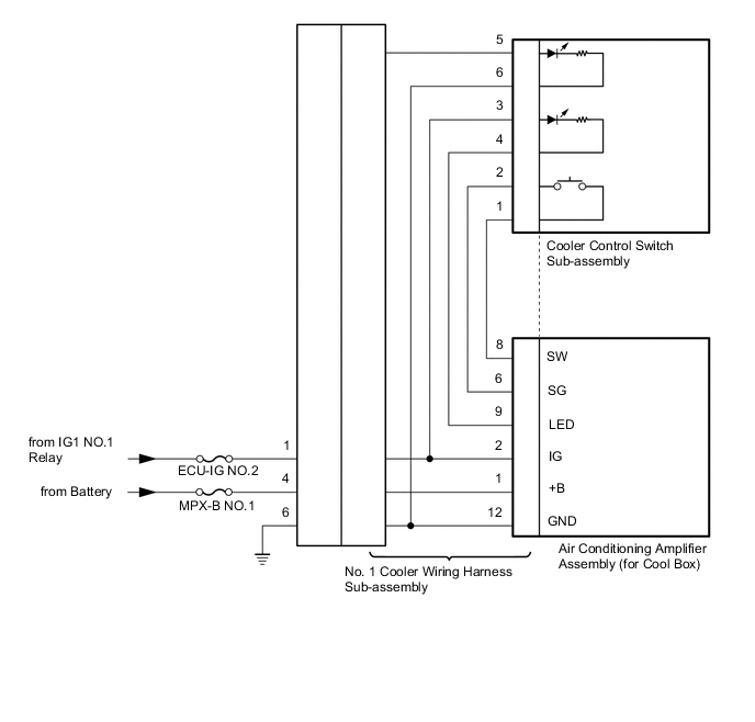
The cooler control switch sub-assembly is the activation switch for the cool box. If the cool box does not activate when the cooler control switch is pushed, there may be a malfunction in the circuit shown below.
WIRING DIAGRAM
CAUTION / NOTICE / HINT
Note
Inspect the fuses for circuits related to this system before performing the following inspection procedure.
PROCEDURE
-
CHECK HARNESS AND CONNECTOR (NO. 1 COOLER WIRING HARNESS SUB-ASSEMBLY - BATTERY)
-
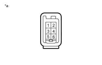
Text in Illustration *a Front view of wire harness connector
(to No. 1 Cooler Wiring Harness Sub-assembly)
Disconnect the No. 1 cooler wiring harness sub-assembly connector.
-
Measure the voltage according to the value(s) in the table below.
Standard Voltage Tester Connection Condition Specified Condition 4 - Body ground Always 11 to 14 V 1 - Body ground Engine switch off Below 1 V 1 - Body ground Engine switch on (IG) 11 to 14 V
NG 
REPAIR OR REPLACE HARNESS OR CONNECTOR
OK 
-
-
CHECK HARNESS AND CONNECTOR (NO. 1 COOLER WIRING HARNESS SUB-ASSEMBLY - BODY GROUND)
-
Text in Illustration *a Front view of wire harness connector
(to No. 1 Cooler Wiring Harness Sub-assembly)
Disconnect the No. 1 cooler wiring harness sub-assembly connector.
-
Measure the resistance according to the value(s) in the table below.
Standard Resistance Tester Connection Condition Specified Condition 6 - Body ground Always Below 1 Ω
NG
REPAIR OR REPLACE HARNESS OR CONNECTOR
OK
-
-
CHECK NO. 1 COOLER WIRING HARNESS SUB-ASSEMBLY
-
Replace the No. 1 cooler wiring harness sub-assembly with a new or known good one.
OK Same problem does not occur.
OK
END (NO. 1 COOLER WIRING HARNESS SUB-ASSEMBLY WAS DEFECTIVE)
NG
-
-
INSPECT COOLER CONTROL SWITCH SUB-ASSEMBLY
-
Remove the cooler control switch sub-assembly Click here.
-
Inspect the cooler control switch sub-assembly Click here.
OK
REPLACE AIR CONDITIONING AMPLIFIER ASSEMBLY (for Cool Box) Click here
NG
REPLACE COOLER CONTROL SWITCH SUB-ASSEMBLY Click here
-