AIR CONDITIONING SYSTEM Cooling Box Sensor Circuit
DESCRIPTION
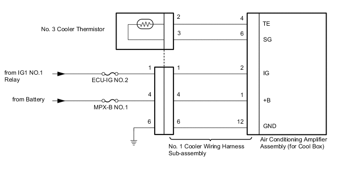
The No. 3 cooler thermistor is installed on the evaporator in the cooling box unit to detect the cooled air temperature that has passed through the evaporator and control the cooling box. It sends appropriate signals to the air conditioning amplifier assembly (for cool box). The resistance of the No. 3 cooler thermistor changes in accordance with the cooled air temperature that has passed through the evaporator. As the temperature decreases, the resistance increases. As the temperature increases, the resistance decreases.
The air conditioning amplifier assembly (for cool box) applies voltage (12 V) to the No. 3 cooler thermistor and reads voltage changes as the resistance of the No. 3 cooler thermistor changes.
WIRING DIAGRAM
CAUTION / NOTICE / HINT
Note
Inspect the fuses for circuits related to this system before performing the following inspection procedure.
PROCEDURE
-
CHECK HARNESS AND CONNECTOR (NO. 1 COOLER WIRING HARNESS SUB-ASSEMBLY - BATTERY)
-
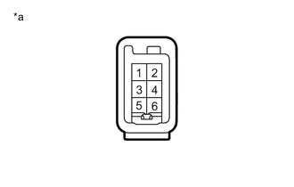
Text in Illustration *a Front view of wire harness connector
(to No. 1 Cooler Wiring Harness Sub-assembly)
Disconnect the No. 1 cooler wiring harness sub-assembly connector.
-
Measure the voltage according to the value(s) in the table below.
Standard Voltage Tester Connection Switch Condition Specified Condition 4 - Body ground Always 11 to 14 V 1 - Body ground Engine switch off Below 1 V 1 - Body ground Engine switch on (IG) 11 to 14 V
NG 
REPAIR OR REPLACE HARNESS OR CONNECTOR
OK 
-
-
CHECK HARNESS AND CONNECTOR (NO. 1 COOLER WIRING HARNESS SUB-ASSEMBLY - BODY GROUND)
-
Disconnect the No. 1 cooler wiring harness sub-assembly connector.
-
Measure the resistance according to the value(s) in the table below.
Standard Resistance Tester Connection Condition Specified Condition 6 - Body ground Always Below 1 Ω
NG
REPAIR OR REPLACE HARNESS OR CONNECTOR
OK
-
-
CHECK NO. 1 COOLER WIRING HARNESS SUB-ASSEMBLY (OPERATION)
-
Replace the No. 1 cooler wiring harness sub-assembly with a new or known good one.
OK Same problem does not occur.
OK
END (NO. 1 COOLER WIRING HARNESS SUB-ASSEMBLY WAS DEFECTIVE)
NG
-
-
INSPECT NO. 3 COOLER THERMISTOR
-
Remove the No. 3 cooler thermistor Click here.
-
Inspect the No. 3 cooler thermistor Click here.
OK
REPLACE AIR CONDITIONING AMPLIFIER ASSEMBLY (for Cool Box) Click here
NG
REPLACE NO. 3 COOLER THERMISTOR Click here
-