AIR CONDITIONING SYSTEM, Diagnostic DTC:B14B9
| DTC Code | DTC Name |
|---|---|
| B14B9 | Open in Ion Generator Circuit |
DESCRIPTION
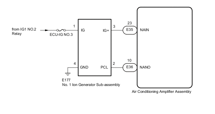
The No. 1 ion generator sub-assembly operates when both the ion generator switch and the blower switch are on. The air conditioning amplifier assembly sends a drive signal to the No. 1 ion generator sub-assembly. When the No. 1 ion generator sub-assembly receives the drive signal and starts to operate, it outputs an operation condition signal to the air conditioning amplifier assembly.
| DTC No. | Detection Item | DTC Detection Condition | DTC Detection Condition | Memory |
|---|---|---|---|---|
| B14B9 | Open in Ion Generator Circuit | Open in ion generator sub-assembly circuit |
|
Memorized (12 sec. or more)* |
-
*: The air conditioning amplifier assembly stores this DTC if the malfunction has occurred for the period of time indicated in the brackets.
WIRING DIAGRAM
CAUTION / NOTICE / HINT
Note
-
If the battery voltage is low, the ion generator may not operate. When "Operation of Electrical Items Restricted." is displayed on the multi-information display in the combination meter assembly, inspect the battery, referring to On-vehicle Inspection for the charging system.
w/o Stop and Start System: Click here
w/ Stop and Start System: Click here
-
If the battery voltage is low, the ion generator may not operate. When "Operation of Electrical Items Restricted." is not displayed on the multi-information display in the combination meter assembly, check the Data List item "Battery Control Count (Body ECU)".
-
Inspect the fuses for circuits related to this system before performing the following procedure.
PROCEDURE
-
PERFORM ACTIVE TEST USING GTS
-
Connect the GTS to the DLC3.
-
Turn the engine switch on (IG).
-
Turn the GTS on.
-
Enter the following menus: Body Electrical / Air Conditioner / Active Test.
-
Perform the Active Test according to the display on the GTS.
Air Conditioner Tester Display Measurement Item Control Range Diagnostic Note Ion Generator No. 1 ion generator sub-assembly OFF or ON - OK No. 1 ion generator sub-assembly operates normally. Result Proceed to OK NG
OK 
REPLACE AIR CONDITIONING AMPLIFIER ASSEMBLY Click here
NG 
-
-
CHECK HARNESS AND CONNECTOR (NO. 1 ION GENERATOR SUB-ASSEMBLY - BATTERY AND BODY GROUND)
-
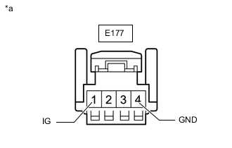
*a Front view of wire harness connector
(to No. 1 Ion Generator Sub-assembly)
Disconnect the No. 1 ion generator sub-assembly connector.
-
Measure the resistance according to the value(s) in the table below.
Standard Resistance Tester Connection Condition Specified Condition E177-4 (GND) - Body ground Always Below 1 Ω -
Measure the voltage according to the value(s) in the table below.
Standard Voltage Tester Connection Condition Specified Condition E177-1 (IG) - Body ground Engine switch off Below 1 V Engine switch on (IG) 11 to 14 V Result Proceed to OK NG
NG
REPAIR OR REPLACE HARNESS OR CONNECTOR
OK
-
-
CHECK HARNESS AND CONNECTOR (NO. 1 ION GENERATOR SUB-ASSEMBLY - AIR CONDITIONING AMPLIFIER ASSEMBLY)
-
Disconnect the E177 No. 1 ion generator sub-assembly connector.
-
Disconnect the E35 and E36 air conditioning amplifier assembly connectors.
-
Measure the resistance according to the value(s) in the table below.
Standard Resistance Tester Connection Condition Specified Condition E177-3 (IG+) - E35-23 (NAIN) Always Below 1 Ω E177-2 (PCL) - E36-10 (NANO) Always Below 1 Ω E177-3 (IG+) or E35-23 (NAIN) - Body ground Always 10 kΩ or higher E177-2 (PCL) or E36-10 (NANO) - Body ground Always 10 kΩ or higher Result Proceed to OK NG
NG
REPAIR OR REPLACE HARNESS AND CONNECTOR
OK
-
-
CHECK AIR CONDITIONING AMPLIFIER ASSEMBLY
-
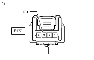
*a Component with harness connected
(No. 1 Ion Generator Sub-assembly)
Measure the voltage according to the value(s) in the table below.
Standard Voltage Tester Connection Condition Specified Condition E177-3 (IG+) - Body ground
-
Engine switch on (IG)
-
Blower switch: LO
-
"nanoe" display: Off
4.75 to 5.25 V Result Proceed to OK NG -
NG
REPLACE AIR CONDITIONING AMPLIFIER ASSEMBLY Click here
OK
-
-
CHECK NO. 1 ION GENERATOR SUB-ASSEMBLY
-
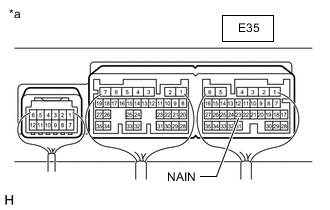
*a Component with harness connected
(Air Conditioning Amplifier Assembly)
Measure the voltage according to the value(s) in the table below.
Standard Voltage Tester Connection Condition Specified Condition E35-23 (NAIN) - Body ground
-
Engine switch on (IG)
-
Blower switch: LO
-
"nanoe" display: On
Below 2.2 V Result Proceed to OK NG -
OK
REPLACE NO. 1 ION GENERATOR SUB-ASSEMBLY Click here
NG
REPLACE AIR CONDITIONING AMPLIFIER ASSEMBLY Click here
-