AIR CONDITIONING SYSTEM, Diagnostic DTC:B1418/18
| DTC Code | DTC Name |
|---|---|
| B1418/18 | Exhaust Gas Sensor Circuit |
DESCRIPTION
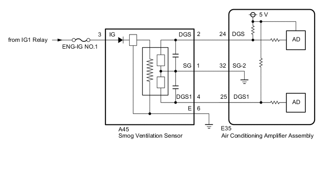
The smog ventilation sensor is installed to the front of the cooler condenser assembly to automatically control the air inlet mode (fresh, recirculation/fresh, and recirculation).
This sensor detects HC and CO in exhaust gasses and transmits signals to the air conditioning amplifier assembly.
| DTC Code | DTC Detection Condition | Trouble Area |
|---|---|---|
| B1418/18 | Open or short in smog ventilation sensor circuit (HC, CO) |
|
WIRING DIAGRAM
CAUTION / NOTICE / HINT
Note
-
Inspect the fuses for circuits related to this system before performing the following inspection procedure.
-
If DTCs B1418/18 and B1461/61 are stored simultaneously, there may be a malfunction in the smog ventilation sensor power source related circuits.
PROCEDURE
-
READ VALUE USING GTS (EMISSION GAS SENSOR)
-
Use the Data List to check if the smog ventilation sensor is functioning properly Click here.
Air Conditioner Tester Display Measurement Item / Range Normal Condition Diagnostic Note Emission Gas Sensor Smog ventilation sensor /
Min.: 0, Max.: 255
Decreases as the gas amount increases - OK The display is as specified in the normal condition. Result Result Proceed to OK (When troubleshooting according to the DTC) A OK (When troubleshooting according to Problem Symptoms Table) B NG C
A 
REPLACE AIR CONDITIONING AMPLIFIER ASSEMBLY Click here
B
PROCEED TO NEXT CIRCUIT INSPECTION SHOWN IN PROBLEM SYMPTOMS TABLE Click here
C 
-
-
CHECK HARNESS AND CONNECTOR (SMOG VENTILATION SENSOR - BODY GROUND)
-
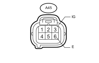
Text in Illustration *a Front view of wire harness connector
(to Smog Ventilation Sensor)
Disconnect the A45 smog ventilation sensor connector.
-
Measure the resistance according to the value(s) in the table below.
Standard Resistance Tester Connection Condition Specified Condition A45-6 (E) - Body ground Always Below 1 Ω -
Measure the voltage according to the value(s) in the table below.
Standard Voltage Tester Connection Condition Specified Condition A45-3 (IG) - Body ground Engine switch off Below 1 V A45-3 (IG) - Body ground Engine switch on (IG) 11 to 14 V
NG
REPAIR OR REPLACE HARNESS OR CONNECTOR
OK
-
-
INSPECT SMOG VENTILATION SENSOR
-
Remove the smog ventilation sensor Click here.
-
Inspect the smog ventilation sensor Click here.
NG
REPLACE SMOG VENTILATION SENSOR Click here
OK
-
-
CHECK HARNESS AND CONNECTOR (SMOG VENTILATION SENSOR - AIR CONDITIONING AMPLIFIER ASSEMBLY)
-
Disconnect the A45 smog ventilation sensor connector.
-
Disconnect the E35 air conditioning amplifier assembly connector.
-
Measure the resistance according to the value(s) in the table below.
Standard Resistance Tester Connection Condition Specified Condition A45-1 (SG) - E35-32 (SG-2) Always Below 1 Ω A45-2 (DGS) - E35-24 (DGS) Always Below 1 Ω A45-1 (SG) or E35-32 (SG-2) - Body ground Always 10 kΩ or higher A45-2 (DGS) or E35-24 (DGS) - Body ground Always 10 kΩ or higher E35-30 (SG-4) - E35-24 (DGS) Always 10 kΩ or higher
OK
REPLACE AIR CONDITIONING AMPLIFIER ASSEMBLY Click here
NG
REPAIR OR REPLACE HARNESS OR CONNECTOR
-