AIR CONDITIONING SYSTEM, Diagnostic DTC:B1419/19
| DTC Code | DTC Name |
|---|---|
| B1419/19 | Rear Room Temperature Sensor Circuit |
DESCRIPTION
-
*1: for LHD
-
*2: for RHD
The cooler thermistor (rear room temperature sensor LH*1 or RH*2) is installed in the rear quarter trim board LH*1 or RH*2 to detect the rear room temperature and control the heater and air conditioner "auto" mode. The resistance of the rear room temperature sensor LH*1 or RH*2 changes in accordance with the cooler thermistor (rear room temperature sensor LH*1or RH*2) seat. As the temperature decreases, the resistance increases. As the temperature increases, the resistance decreases.
The air conditioning amplifier assembly applies a voltage (5 V) to the cooler thermistor (rear room temperature sensor LH*1 or RH*2) and reads voltage changes as changes in the resistance of the cooler thermistor (rear room temperature sensor LH* or RH*2)
| DTC Code | DTC Detection Condition | Trouble Area |
|---|---|---|
| B1419/19 | An open or short in the cooler thermistor (rear room temperature sensor LH*1 or RH*2) circuit. |
|
WIRING DIAGRAM
-
for LHD:
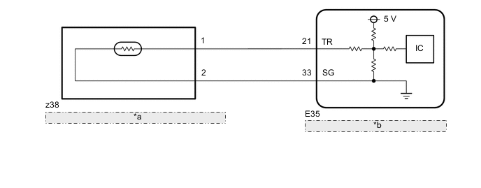
*a Cooler Thermistor (Rear Room Temperature Sensor LH) *b Air Conditioning Amplifier Assembly -
for RHD:
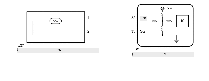
*a TSET *b Cooler Thermistor (Rear Room Temperature Sensor RH) *c Air Conditioning Amplifier Assembly
PROCEDURE
-
READ VALUE USING GTS (ROOM TEMP SENSOR [REAR])
-
*1: for LHD
-
*2: for RHD
-
Use the Data List to check if the rear room temperature sensor LH*1 or RH*2 is functioning properly Click here.
Air Conditioner Tester Display Measurement Item/Range Normal Condition Diagnostic Note Room Temp Sensor (Rear) Cooler thermistor (rear room temperature sensor for LH*1,RH*2) / Min.: -6.5°C (20.3°F), Max.: 57.25°C (135.05°F) Actual rear room temperature for LH*1 or RH*2 displayed Cooler thermistor (rear room temperature sensor for LH*1 or RH*2) system malfunction:
-
Open in the circuit: -6.5°C (20.3°F)
-
Short in the circuit: 57.25°C (135.05°F)
OK The display is as specified in the normal condition. Result Result Proceed to OK (When troubleshooting according to the DTC) A OK (When troubleshooting according to Problem Symptoms Table) B NG C -
A 
REPLACE AIR CONDITIONING AMPLIFIER ASSEMBLY Click here
B
PROCEED TO NEXT CIRCUIT INSPECTION SHOWN IN PROBLEM SYMPTOMS TABLE Click here
C 
-
-
INSPECT COOLER THERMISTOR (REAR ROOM TEMPERATURE SENSOR)
-
for LHD:
-
Remove the cooler thermistor (rear room temperature sensor LH) Click here.
-
-
for RHD
-
Remove the cooler thermistor (rear room temperature sensor RH) Click here.
-
-
Inspect the cooler thermistor (rear room temperature sensor) Click here.
Result Result Proceed to OK A NG (for LHD) B NG (for RHD) C
B
REPLACE COOLER THERMISTOR (REAR ROOM TEMPERATURE SENSOR LH) Click here
C
REPLACE COOLER THERMISTOR (REAR ROOM TEMPERATURE SENSOR RH) Click here
A
-
-
CHECK HARNESS AND CONNECTOR (COOLER THERMISTOR [REAR ROOMTEMPERATURE SENSOR] - AIR CONDITIONING AMPLIFIER ASSEMBLY)
-
for LHD:
-
Disconnect the z38 cooler thermistor (rear room temperature sensor LH) connector.
-
Disconnect the E35 air conditioning amplifier assembly connector.
-
Measure the resistance according to the value(s) in the table below.
Standard Resistance Tester Connection Condition Specified Condition z38-1 - E35-21 (TR) Always Below 1 Ω z38-2 - E35-33 (SG) Always Below 1 Ω z38-1 - z38-2 Always 10 kΩ or higher z38-1 or E35-21 (TR) - Body ground Always 10 kΩ or higher z38-2 or E35-33 (SG) - Body ground Always 10 kΩ or higher
-
-
for RHD:
-
Disconnect the z37 cooler thermistor (rear room temperature sensor RH) connector.
-
Disconnect the E35 air conditioning amplifier assembly connector.
-
Measure the resistance according to the value(s) in the table below.
Standard Resistance Tester Connection Condition Specified Condition z37-1 - E35-22 (TEST) Always Below 1 Ω z37-2 - E35-33 (SG) Always Below 1 Ω z37-1 - z37-2 Always 10 kΩ or higher z37-1 or E35-22 (TEST) - Body ground Always 10 kΩ or higher z37-2 or E35-33 (SG) - Body ground Always 10 kΩ or higher
-
OK
REPLACE AIR CONDITIONING AMPLIFIER ASSEMBLY Click here
NG
REPAIR OR REPLACE HARNESS OR CONNECTOR
-