AIR CONDITIONING SYSTEM, Diagnostic DTC:B1497/97
| DTC Code | DTC Name |
|---|---|
| B1497/97 | BUS IC Communication Malfunction |
DESCRIPTION
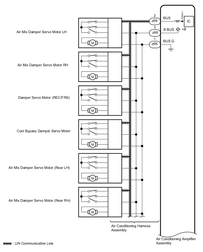
The air conditioning harness assembly connects the air conditioning amplifier assembly and each servo motor. The air conditioning amplifier assembly supplies power and sends operation instructions to each servo motor through the air conditioning harness assembly. Each servo motor sends the damper position information to the air conditioning amplifier assembly.
| DTC Code | DTC Detection Condition | Trouble Area |
|---|---|---|
| B1497/97 | An open or error in the communication line. |
|
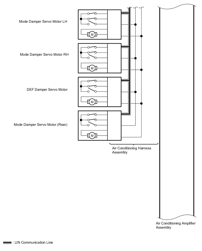
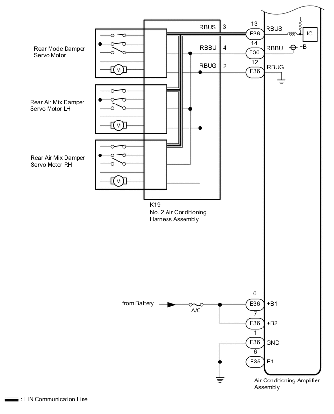
WIRING DIAGRAM
CAUTION / NOTICE / HINT
Note
Inspect the fuses for circuits related to this system before performing the following inspection procedure.
PROCEDURE
-
CHECK FOR DTC
-
Clear the DTCs Click here.
-
Check for DTCs Click here.
OK DTC B1497/97 is not output.
OK 
USE SIMULATION METHOD TO CHECK Click here
NG 
-
-
CHECK HARNESS AND CONNECTOR (AIR CONDITIONING AMPLIFIER ASSEMBLY - BATTERY AND BODY GROUND)
-
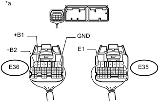
Text in Illustration *a Front view of wire harness connector
(to Air Conditioning Amplifier Assembly)
Disconnect the air conditioning amplifier assembly connector.
-
Measure the resistance according to the value(s) in the table below.
Standard Resistance Tester Connection Condition Specified Condition E35-6 (E1) - Body ground Always Below 1 Ω E36-1 (GND) - Body ground Always Below 1 Ω -
Measure the voltage according to the value(s) in the table below.
Standard Voltage Tester Connection Condition Specified Condition E36-6 (+B1) - Body ground Always 11 to 14 V E36-7 (+B2) - Body ground Always 11 to 14 V
NG
REPAIR OR REPLACE HARNESS OR CONNECTOR
OK
-
-
PERFORM ACTIVE TEST USING GTS (DAMPER SERVO MOTOR)
-
Select the Active Test, use the GTS to generate a control command, and then check that the servo motors operates Click here.
Air Conditioner Tester Display Test Part Control Range Diagnostic Note Air Mix Servo Targ Pulse(D) Air mix damper servo motor LH pulse Min.: 128, Max.: 383
-
Operates between 249 to 331 (for LHD)
-
Operates between 181 to 263 (for RHD)
Air Mix Servo Targ Pulse(P) Air mix damper servo motor RH pulse Min.: 128, Max.: 383
-
Operates between 181 to 263 (for LHD)
-
Operates between 249 to 331 (for RHD)
Air Outlet Servo Pulse (D) Mode damper servo motor LH*1 or RH*2 Pulse Min.: 128, Max.: 383 Operates between 143 to 254 Air Inlet Damper Targ Pulse Mode damper servo motor (REC/FRS) pulse Min.: 128, Max.: 383 Operates between 258 to 286 Cool Air Bypass Pulse Cool bypass damper servo motor pulse Min.: 128, Max.: 383 Operates between 225 to 254 Rear Air Mix Servo Targ Pulse Rear air mix damper servo motor LH*1 or RH*2 Pulse Min.: 128, Max.: 383
-
Operates between 254 to 299 (for LHD)
-
Operates between 213 to 258 (for RHD)
Air Outlet Servo Pulse (P) Mode damper servo motor RH*1 or LH*2 pulse Min.: 128, Max.: 383
-
Operates between 143 to 254 (for LHD)
-
Operates between 258 to 369 (for RHD)
A/M Servo Puls(F&R D) Air mix damper servo motor (rear LH*1 or RH*2) pulse Min.: 128, Max.: 383
-
Operates between 262 to 290 (for LHD)
-
Operates between 222 to 250 (for RHD)
A/M Servo Puls(F&R P) Air mix damper servo motor (rear RH*1 or LH*2) pulse Min.: 128, Max.: 383
-
Operates between 222 to 250 (for LHD)
-
Operates between 262 to 290 (for RHD)
A/O Servo Pulse(F&R D) Mode damper servo motor (rear) pulse Min.: 128, Max.: 383 Operates between 258 to 328 A/O Servo Pulse(Rr D) Rear mode damper servo motor pulse Min.: 128, Max.: 383 Operates between 258 to 328 DEF A/O Servo Pulse(D) DEF mode damper servo motor pulse Min.: 128, Max.: 383 Operates between 258 to 328 Rear A/M Servo Pulse(P) Rear air mix damper servo motor RH pulse Min.: 128, Max.: 383
-
Operates between 213 to 258 (for LHD)
-
Operates between 254 to 299 (for RHD)
-
*1: for LHD
-
*2: for RHD
OK Arm of the damper servo motor selected in the Active Test moves smoothly. Result Result Proceed to Any front damper servo motor is malfunctioning A All front damper servo motors are malfunctioning B Any rear damper servo motor is malfunctioning C All rear damper servo motors are malfunctioning D -
B 
CHECK HARNESS AND CONNECTOR (NO. 2 AIR CONDITIONING HARNESS ASSEMBLY - AIR CONDITIONING AMPLIFIER ASSEMBLY) Click here
C
CHECK DAMPER SERVO MOTOR (CONNECTED TO NO. 2 AIR CONDITIONING HARNESS ASSEMBLY) Click here
D
CHECK NO. 2 AIR CONDITIONING HARNESS ASSEMBLY Click here
A
-
-
CHECK DAMPER SERVO MOTOR (CONNECTED TO AIR CONDITIONING HARNESS ASSEMBLY)
-
Replace the malfunctioning damper servo motor connected to air conditioning harness assembly Click here.
Tech Tips
Since the servo motor cannot be inspected while it is removed from the vehicle, replace the servo motor with a new one and check that the condition returns to normal.
-
Clear the DTCs Click here.
-
Check for DTCs Click here.
OK DTC B1497/97 is not output.
OK
END (DAMPER SERVO MOTOR WAS DEFECTIVE)
NG
-
-
CHECK AIR CONDITIONING HARNESS ASSEMBLY
-
Replace the air conditioning harness assembly with a new or known good one. Click here
-
Clear the DTCs Click here.
-
Check for DTCs Click here.
OK DTC B1497/97 is not output.
OK
END (AIR CONDITIONING HARNESS ASSEMBLY WAS DEFECTIVE)
NG
REPLACE AIR CONDITIONING AMPLIFIER ASSEMBLY Click here
-
-
CHECK HARNESS AND CONNECTOR (NO. 2 AIR CONDITIONING HARNESS ASSEMBLY - AIR CONDITIONING AMPLIFIER ASSEMBLY)
-
Disconnect the K19 No. 2 air conditioning harness assembly connector.
-
Disconnect the E36 air conditioning amplifier assembly connector.
-
Measure the resistance according to the value(s) in the table below.
Standard Resistance Tester Connection Condition Specified Condition K19-2 (RBUG) - E36-12 (RBUG) Always Below 1 Ω K19-3 (RBUS) - E36-13 (RBUS) Always Below 1 Ω K19-4 (RBBU) - E36-14 (RBBU) Always Below 1 Ω K19-2 (RBUG) or E36-12 (RBUG) - Body ground Always 10 kΩ or higher K19-3 (RBUS) or E36-13 (RBUS) - Body ground Always 10 kΩ or higher K19-4 (RBBU) or E36-14 (RBBU) - Body ground Always 10 kΩ or higher
NG
REPAIR OR REPLACE HARNESS OR CONNECTOR
OK
-
-
CHECK DAMPER SERVO MOTOR (CONNECTED TO NO. 2 AIR CONDITIONING HARNESS ASSEMBLY)
-
Replace the malfunctioning damper servo motor connected to No. 2 air conditioning harness connector Click here.
Tech Tips
Since the servo motor cannot be inspected while it is removed from the vehicle, replace the servo motor with a new one and check that the condition returns to normal.
-
Clear the DTCs Click here.
-
Check for DTCs Click here.
OK DTC B1497/97 is not output.
OK
END (DAMPER SERVO MOTOR WAS DEFECTIVE)
NG
REPLACE AIR CONDITIONING AMPLIFIER ASSEMBLY Click here
-
-
CHECK NO. 2 AIR CONDITIONING HARNESS ASSEMBLY
-
Replace the No. 2 air conditioning harness assembly with a new or known good one Click here.
-
Clear the DTCs Click here.
-
Check for DTCs Click here.
OK DTC B1497/97 is not output.
OK
END (NO. 2 AIR CONDITIONING HARNESS ASSEMBLY WAS DEFECTIVE)
NG
REPLACE AIR CONDITIONING AMPLIFIER ASSEMBLY Click here
-