SEAT HEATER SYSTEM, Diagnostic DTC:B14C1
| DTC Code | DTC Name |
|---|---|
| B14C1 | Front Left Seat Heat Sensor Circuit |
DESCRIPTION
Output to the front seat cushion heater assembly LH temperature sensor stops if one of the following occurs: 1) the temperature sensor is open or shorted; or 2) the temperature sensor is damaged and its output value does not change.
| DTC Code | DTC Detection Condition | Trouble Area |
|---|---|---|
| B14C1 | Seat heater temperature sensor malfunction |
|
WIRING DIAGRAM
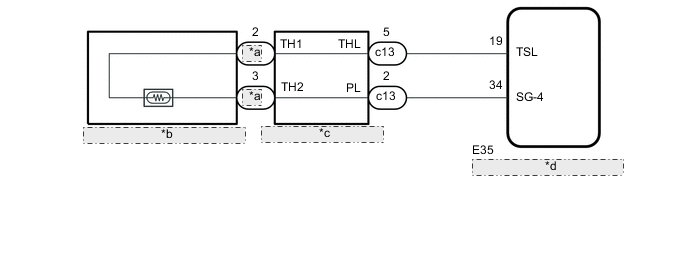
| *a | SHL |
| *b | Front Seat Cushion Heater Assembly LH |
| *c | Seat Heater Control Sub-assembly LH |
| *d | Air Conditioning Amplifier Assembly |
PROCEDURE
-
CLEAR DTC
-
Clear the DTCs Click here.
NEXT 
-
-
CHECK FOR DTC
-
Check for DTCs Click here.
OK DTC B14C1 is not output.
OK 
USE SIMULATION METHOD TO CHECK Click here
NG
-
-
READ VALUE USING GTS (FL SEAT HEATER TEMPERATURE)
-
Connect the GTS to the DLC3.
-
Turn the engine switch on (IG).
-
Turn the GTS on.
-
Enter the following menus: Body Electrical / Air Conditioner / Data List.
-
Read the Data List according to the display on the GTS.
Air Conditioner Tester Display Measurement Item/Display Range Normal Condition Diagnostic Note FL Seat Heater Temperature Front seat LH side seat heater temperature -29.7°C to 59.55°C Within range from 32 to 43°C (89 to 109°F) Front seat heater is on
OK
REPLACE AIR CONDITIONING AMPLIFIER ASSEMBLY Click here
NG
-
-
INSPECT FRONT SEAT CUSHION HEATER ASSEMBLY LH
-
Remove the front seat cushion heater assembly LH Click here.
-
Inspect the front seat cushion heater assembly LH Click here.
NG
REPLACE FRONT SEAT CUSHION HEATER ASSEMBLY LH Click here
OK
-
-
INSPECT SEAT HEATER CONTROL SUB-ASSEMBLY LH
-
Text in Illustration *a Seat Heater Control Sub-assembly LH
(to Air Conditioning Amplifier Assembly)
*b Seat Heater Control Sub-assembly LH
(to Front Seat Cushion Heater Assembly LH)
Remove the seat heater control sub-assembly LH connector Click here.
-
Measure the resistance according to the value(s) in the table below.
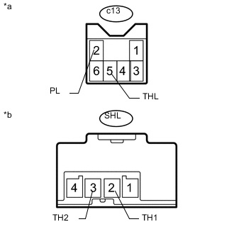
Standard Resistance Tester Connection Condition Specified Condition c13-5 (THL) - SHL-2 (TH1) Always Below 1 Ω c13-2 (PL) - SHL-3 (TH2) Always Below 1 Ω c13-5 (THL) or SHL-2 (TH1) - Body ground Always 10 kΩ or higher c13-2 (PL) or SHL-3 (TH2) - Body ground Always 10 kΩ or higher
NG
REPLACE SEAT HEATER CONTROL SUB-ASSEMBLY LH
OK
-
-
CHECK HARNESS AND CONNECTOR (AIR CONDITIONING AMPLIFIER ASSEMBLY - SEAT HEATER CONTROL SUB-ASSEMBLY LH)
-
Disconnect the E35 air conditioning amplifier assembly connector.
-
Disconnect the c13 seat heater control sub-assembly LH connector.
-
Measure the resistance according to the value(s) in the table below.
Standard Resistance Tester Connection Condition Specified Condition E35-19 (TSL) - c13-5 (THL) Always Below 1 Ω E35-34 (SG-4) - c13-2 (PL) - Always Below 1 Ω E35-19 (TSL) or c13-5 (THL) - Body ground Always 10 kΩ or higher E35-34 (SG-4) or c13-2 (PL) - Body ground Always 10 kΩ or higher
OK
REPLACE AIR CONDITIONING AMPLIFIER ASSEMBLY Click here
NG
REPAIR OR REPLACE HARNESS OR CONNECTOR
-