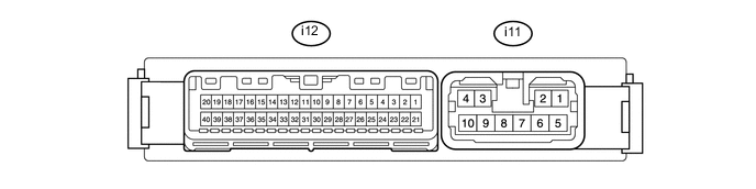
REAR POWER SEAT CONTROL SYSTEM(for Rear No. 2 Seat with Automatic Folding-up Function) TERMINALS OF ECU
-
CHECK FOLD SEAT CONTROL ECU LH
-
Disconnect the i11 and i12 ECU connectors.
-
Measure the voltage and resistance according to the value(s) in the table below.
Terminal No. (Symbol) Wiring Color Terminal Description Condition Specified Condition i11-4 (+B) - i11-8 (GND) R - W-B Power source Always 11 to 14 V i11-8 (GND) - Body ground W-B - Body ground Ground Always Below 1 Ω i12-1 (ECUB) - i11-8 (GND) R - W-B Power source Always 11 to 14 V i12-3 (IG) - i11-8 (GND) B - W-B Engine switch signal Engine switch on (IG) 6 V or higher Engine switch off Below 2 V If the result is not as specified, there may be a malfunction on the wire harness side.
-
Reconnect the i11 and i12 ECU connectors.
-
Measure the voltage and resistance according to the value(s) in the table below.
Terminal No. (Symbol) Wiring Color Terminal Description Condition Specified Condition i11-1 (FLD+) - i11-8 (GND) G - W-B Folding-up motor LH operation signal Rear No. 2 seat LH folding-up operation 9 to 14 V i11-2 (ACT+) - i11-8 (GND) B - W-B Closer motor LH operation signal Closer motor LH lock operation 9 to 14 V i11-3 (FACT) - i11-8 (GND) B - W-B Floor release motor LH operation signal Floor release motor LH operating 9 to 14 V i11-5 (FLD-) - i11-8 (GND) R - W-B Folding-up motor LH operation signal Rear No. 2 seat LH return operation 9 to 14 V i11-6 (ACT-) - i11-8 (GND) W - W-B Closer motor LH operation signal Closer motor LH unlock operation 9 to 14 V i11-7 (RACT) - i11-8 (GND) L - W-B No. 1 back release motor LH operation signal No. 1 back release motor LH operating 9 to 14 V No. 2 back release motor LH operation signal No. 2 back release motor LH operating i12-5 (BDCY) - i11-8 (GND) W - W-B Back door courtesy switch signal Back door open Below 1 V Back door closed 9 to 14 V i12-14 (TBL) - i11-8 (GND) Y - W-B Fold seat switch signal (Table switch LH) Back door open
Fold seat switch (Table switch LH) off
9 to 14 V Back door open
Fold seat switch (Table switch LH) on
Below 1 V i12-15 (RTRN) - i11-8 (GND) GR - W-B Fold seat switch signal (Seat switch LH) Back door open
Fold seat switch (Seat switch LH) off
9 to 14 V Back door open
Fold seat switch (Seat switch LH) on
Below 1 V i12-16 (FOLD) - i11-8 (GND) G - W-B Fold seat switch signal (Fold switch LH) Back door open
Fold seat switch (Fold switch LH) off
9 to 14 V Back door open
Fold seat switch (Fold switch LH) on
Below 1 V i12-17 (LOPN) - i11-8 (GND) V - W-B No. 1 closer motor position slide switch LH signal No. 1 closer motor position slide switch LH off 9 to 14 V No. 1 closer motor position slide switch LH on Below 1 V i12-19 (LCTY) - i11-8 (GND) L - W-B Seat fixing lock switch LH signal Seat fixing lock switch LH off 9 to 14 V Seat fixing lock switch LH on Below 1 V i12-20 (LCLS) - i11-8 (GND) P - W-B No. 2 closer motor position slide switch LH signal No. 2 closer motor position slide switch LH off 9 to 14 V No. 2 closer motor position slide switch LH on Below 1 V i12-23 (SFLD) - i12-30 (SG1) W - B Seat cushion position sensor LH signal Folding-up motor LH operating Pulse generation i12-24 (SV1) - i11-8 (GND) G - W-B Power supply for seat cushion position sensor LH Back door open 4.8 V or higher Back door closed Below 1 V i12-30 (SG1) - Body ground B - Body ground Ground for seat cushion position sensor LH Always Below 1 Ω i12-32 (P) - i11-8 (GND) G - W-B Park/neutral position switch signal Engine switch on (IG)
Park/neutral position switch in P position
6 V or higher Engine switch on (IG)
Park/neutral position switch not in P position
Below 2 V i12-34 (IND2) - i11-8 (GND) B - W-B 3rd seat indicator signal Engine switch on (IG)
3rd seat indicator off
9 to 14 V Engine switch on (IG)
3rd seat indicator on
Below 1 V i12-35 (IND1) - i11-8 (GND) W - W-B Fold seat switch indicator LH signal Back door open
Fold seat switch indicator LH off
Below 1 V Back door open
Fold seat switch indicator LH on
8.6 to 14 V i12-37 (LCKF) - i11-8 (GND) SB - W-B No. 1 floor striker limit switch LH signal No. 1 floor striker limit switch LH off 9 to 14 V No. 1 floor striker limit switch LH on Below 1 V i12-38 (LCKB) - i11-8 (GND) L - W-B No. 1 seatback lock switch LH signal No. 1 seatback lock switch LH off 9 to 14 V No. 1 seatback lock switch LH on Below 1 V No. 2 seatback lock switch LH signal No. 2 seatback lock switch LH off 9 to 14 V No. 2 seatback lock switch LH on Below 1 V i12-39 (ERAB) - i11-8 (GND) BE - W-B Seatback area switch LH signal Seatback area switch LH off 9 to 14 V Seatback area switch LH on Below 1 V i12-40 (LCK2) - i11-8 (GND) R - W-B No. 2 floor striker limit switch LH signal No. 2 floor striker limit switch LH off 9 to 14 V No. 2 floor striker limit switch LH on Below 1 V If the result is not as specified, the fold seat control ECU may have a malfunction.
-
-
CHECK FOLD SEAT CONTROL ECU RH

-
Disconnect the i3 and i4 ECU connectors.
-
Measure the voltage and resistance according to the value(s) in the table below.
Terminal No. (Symbol) Wiring Color Terminal Description Condition Specified Condition i3-4 (+B) - i3-8 (GND) L- W-B Power source Always 11 to 14 V i3-8 (GND) - Body ground W-B - Body ground Ground Always Below 1 Ω i4-1 (ECUB) - i3-8 (GND) R - W-B Power source Always 11 to 14 V i4-3 (IG) - i3-8 (GND) G - W-B Engine switch signal Engine switch on (IG) 6 V or higher Engine switch off Below 2 V If the result is not as specified, there may be a malfunction on the wire harness side.
-
Reconnect the i3 and i4 ECU connectors.
-
Measure the voltage and resistance according to the value(s) in the table below.
Terminal No. (Symbol) Wiring Color Terminal Description Condition Specified Condition i3-1 (FLD+) - i3-8 (GND) G - W-B Folding-up motor RH operation signal Rear No. 2 seat RH folding-up operation 9 to 14 V i3-2 (ACT+) - i3-8 (GND) B - W-B Closer motor RH operation signal Closer motor RH lock operation 9 to 14 V i3-3 (FACT) - i3-8 (GND) B - W-B Floor release motor RH operation signal Floor release motor RH operating 9 to 14 V i3-5 (FLD-) - i3-8 (GND) R - W-B Folding-up motor RH operation signal Rear No. 2 seat RH return operation 9 to 14 V i3-6 (ACT-) - i3-8 (GND) W - W-B Closer motor RH operation signal Closer motor RH unlock operation 9 to 14 V i3-7 (RACT) - i3-8 (GND) L - W-B No. 1 back release motor RH operation signal No. 1 back release motor RH operating 9 to 14 V No. 2 back release motor RH operation signal No. 2 back release motor RH operating i4-5 (BDCY) - i3-8 (GND) W - W-B Back door courtesy switch signal Back door open Below 1 V Back door closed 9 to 14 V i4-14 (TBL) - i3-8 (GND) P - W-B Fold seat switch signal (Table switch RH) Back door open
Fold seat switch (Table switch RH) off
9 to 14 V Back door open
Fold seat switch (Table switch RH) on
Below 1 V i4-15 (RTRN) - i3-8 (GND) GR - W-B Fold seat switch signal (Seat switch RH) Back door open
Fold seat switch (Seat switch RH) off
9 to 14 V Back door open
Fold seat switch (Seat switch RH) on
Below 1 V i4-16 (FOLD) - i3-8 (GND) G - W-B Fold seat switch signal (Fold switch RH) Back door open
Fold seat switch (Fold switch RH) off
9 to 14 V Back door open
Fold seat switch (Fold switch RH) on
Below 1 V i4-17 (LOPS) - i3-8 (GND) V - W-B No. 1 closer motor position slide switch RH signal No. 1 closer motor position slide switch RH off 9 to 14 V No. 1 closer motor position slide switch RH on Below 1 V i4-19 (LCTY) - i3-8 (GND) L - W-B Seat fixing lock switch RH signal Seat fixing lock switch RH off 9 to 14 V Seat fixing lock switch RH on Below 1 V i4-20 (LCLS) - i3-8 (GND) P - W-B No. 2 closer motor position slide switch RH signal No. 2 closer motor position slide switch RH off 9 to 14 V No. 2 closer motor position slide switch RH on Below 1 V i4-23 (SFLD) - i4-30 (SG1) W - B Seat cushion position sensor RH signal Folding-up motor RH operating Pulse generation i4-24 (SV1) - i3-8 (GND) G - W-B Power supply for seat cushion position sensor RH Back door open 4.8 V or higher Back door closed Below 1 V i4-30 (SG1) - Body ground B - Body ground Ground for seat cushion position sensor RH Always Below 1 Ω i4-32 (P) - i3-8 (GND) G - W-B Park/neutral position switch signal Engine switch on (IG)
Park/neutral position switch in P position
6 V or higher Engine switch on (IG)
Park/neutral position switch not in P position
Below 2 V i4-34 (IND2) - i3-8 (GND) B - W-B 3rd seat indicator signal Engine switch on (IG)
3rd seat indicator off
9 to 14 V Engine switch on (IG)
3rd seat indicator on
Below 1 V i4-35 (IND1) - i3-8 (GND) W - W-B Fold seat switch indicator RH signal Back door open
Fold seat switch indicator RH off
Below 1 V Back door open
Fold seat switch indicator RH on
8.6 to 14 V i4-37 (LCKF) - i3-8 (GND) SB - W-B No. 1 floor striker limit switch RH signal No. 1 floor striker limit switch RH off 9 to 14 V No. 1 floor striker limit switch RH on Below 1 V i4-38 (LCKB) - i3-8 (GND) L - W-B No. 1 seatback lock switch RH signal No. 1 seatback lock switch RH off 9 to 14 V No. 1 seatback lock switch RH on Below 1 V No. 2 seatback lock switch RH signal No. 2 seatback lock switch RH off 9 to 14 V No. 2 seatback lock switch RH on Below 1 V i4-39 (ERAB) - i3-8 (GND) BE - W-B Seatback area switch RH signal Seatback area switch RH off 9 to 14 V Seatback area switch RH on Below 1 V i4-40 (LCK2) - i3-8 (GND) R - W-B No. 2 floor striker limit switch RH signal No. 2 floor striker limit switch RH off 9 to 14 V No. 2 floor striker limit switch RH on Below 1 V If the result is not as specified, the fold seat control ECU may have a malfunction.
-