FRONT POWER SEAT CONTROL SYSTEM One or more Power Seat Motors do not Operate
DESCRIPTION
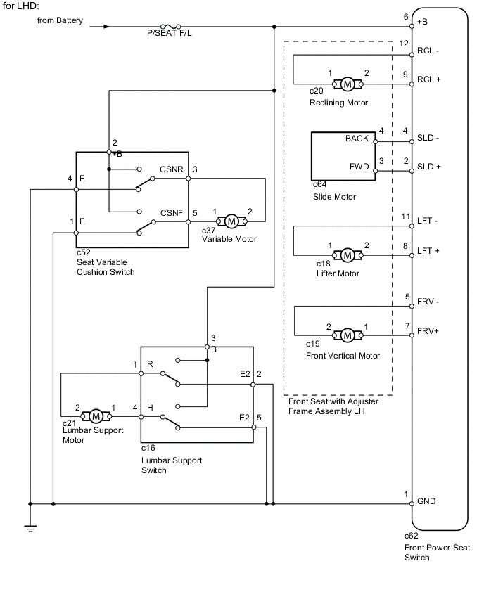
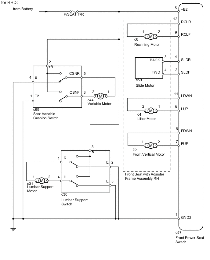
When the front power seat switch is operated, a command signal is sent to the power seat switch. The power seat switch then controls the appropriate seat motor as needed. The power seat switch is designed so that a malfunction of the seat memory system will not interfere with manual seat control.
WIRING DIAGRAM
CAUTION / NOTICE / HINT
Note
Inspect the fuses for circuits related to this system before performing the following inspection procedure.
PROCEDURE
-
CHECK FRONT POWER SEAT OPERATION
-
Check that each function of the power seat operates normally by using the front power seat switches.
Result Result Proceed to All front power seat switch operations are malfunctioning except lumbar support switch and seat variable cushion switch operation A Only lumbar support switch operation is malfunctioning B Only seat variable cushion switch operation is malfunctioning C
B 
INSPECT LUMBAR SUPPORT SWITCH Click here
C
INSPECT SEAT VARIABLE CUSHION SWITCH Click here
A 
-
-
READ VALUE USING GTS (FRONT POWER SEAT SWITCH)
-
Using the GTS, read the Data List.
Driver Seat Item Measurement Item/Display (Range) Normal Condition Diagnostic Note Reclining Rear Reclining switch signal (Rearward) / ON or OFF ON: Reclining switch (Rearward) on
OFF: Reclining switch (Rearward) off
- Reclining Front Reclining switch signal (Forward) / ON or OFF ON: Reclining switch (Forward) on
OFF: Reclining switch (Forward) off
- Front Vertical Down Front vertical switch signal (Downward) / ON or OFF ON: Front vertical switch (Downward) on
OFF: Front vertical switch (Downward) off
- Front Vertical Up Front vertical switch signal (Upward) / ON or OFF ON: Front vertical switch (Upward) on
OFF: Front vertical switch (Upward) off
- Lifter Switch Down Lifter switch signal (Downward) / ON or OFF ON: Lifter switch (Downward) on
OFF: Lifter switch (Downward) off
- Lifter Switch Up Lifter switch signal (Upward) / ON or OFF ON: Lifter switch (Upward) on
OFF: Lifter switch (Upward) off
- Slide Rear Sliding switch signal (Rearward) / ON or OFF ON: Sliding switch (Rearward) on
OFF: Sliding switch (Rearward) off
- Slide Front Sliding switch signal (Forward) / ON or OFF ON: Sliding switch (Forward) on
OFF: Sliding switch (Forward) off
- OK On GTS screen, each item changes between ON and OFF according to above chart.
NG 
REPLACE FRONT POWER SEAT SWITCH Click here
OK
-
-
PERFORM ACTIVE TEST USING GTS (FRONT POWER SEAT MOTOR)
-
Using the GTS, perform the Active Test.
Driver Seat Tester Display Test Part Control Range Diagnostic Note Seat Reclining Seat reclining operation Front / OFF / Rear - Front Vertical Operation Seat front vertical operation Up / OFF / Down - Lifter Operation Seat lifter operation Up / OFF / Down - Seat Slide Operation Seat sliding operation Front / OFF / Rear - OK The power seat motors operate normally.
OK
REPLACE FRONT POWER SEAT SWITCH Click here
NG
-
-
INSPECT FRONT SEAT WITH ADJUSTER FRAME ASSEMBLY (FRONT POWER SEAT MOTOR)
-
Remove the front seat with adjuster frame LH (for LHD) Click here.
-
Remove the front seat with adjuster frame RH (for RHD) Click here.
-
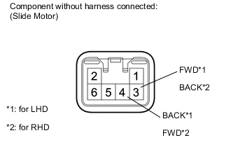
Check operation of the slide motor.
-
Check if the seat moves smoothly when the battery is connected to the slide motor connector terminals.
OK for LHD Measurement Condition Specified Condition Battery positive (+) → 3 (FWD)
Battery negative (-) → 4 (BACK)
Forward Battery positive (+) → 4 (BACK)
Battery negative (-) → 3 (FWD)
Rearward for RHD Measurement Condition Specified Condition Battery positive (+) → 4 (FWD)
Battery negative (-) → 3 (BACK)
Forward Battery positive (+) → 3 (BACK)
Battery negative (-) → 4 (FWD)
Rearward
-
-

*1 Component without harness connected: (Front Vertical Motor) Check operation of the front vertical motor.
-
Check if the seat moves smoothly when the battery is connected to the front vertical motor connector terminals.
OK for LHD Measurement Condition Specified Condition Battery positive (+) → 1
Battery negative (-) → 2
Upward Battery positive (+) → 2
Battery negative (-) → 1
Downward for RHD Measurement Condition Specified Condition Battery positive (+) → 2
Battery negative (-) → 1
Upward Battery positive (+) → 1
Battery negative (-) → 2
Downward
-
-

*1 Component without harness connected: (Lifter Motor) Check operation of the lifter motor.
-
Check if the seat moves smoothly when the battery is connected to the lifter motor connector terminals.
OK for LHD Measurement Condition Specified Condition Battery positive (+) → 2
Battery negative (-) → 1
Upward Battery positive (+) → 1
Battery negative (-) → 2
Downward for RHD Measurement Condition Specified Condition Battery positive (+) → 1
Battery negative (-) → 2
Upward Battery positive (+) → 2
Battery negative (-) → 1
Downward
-
-

*1 Component without harness connected: (Reclining Motor) Check operation of the reclining motor.
-
Check if the seat moves smoothly when the battery is connected to the reclining motor connector terminals.
OK Measurement Condition Specified Condition Battery positive (+) → 2
Battery negative (-) → 1
Forward Battery positive (+) → 1
Battery negative (-) → 2
Rearward
Result Result Proceed to OK A NG (for LHD) B NG (for RHD) C -
B
REPLACE FRONT SEAT WITH ADJUSTER FRAME ASSEMBLY LH Click here
C
REPLACE FRONT SEAT WITH ADJUSTER FRAME ASSEMBLY RH Click here
A
-
-
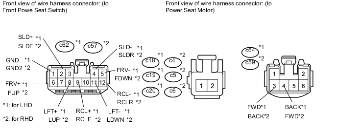
CHECK HARNESS AND CONNECTOR (FRONT POWER SEAT SWITCH - POWER SEAT MOTOR)
-
*1: for LHD
-
*2: for RHD
-
Disconnect the c62*1 or c57*2 front power seat switch connector.
-
Disconnect the c18*1, c19*1, c20*1, c64*1 or c4*2, c5*2, c6*2, c59*2 motor connectors.
-
Measure the resistance according to the value(s) in the table below.
Standard Resistance for LHD Tester Connection Condition Specified Condition c62-4 (SLD-) - c64-4 (BACK) Always Below 1 Ω c62-2 (SLD+) - c64-3 (FWD) Always Below 1 Ω c62-5 (FRV-) - c19-2 Always Below 1 Ω c62-7 (FRV+) - c19-1 Always Below 1 Ω c62-11 (LFT-) - c18-1 Always Below 1 Ω c62-8 (LFT+) - c18-2 Always Below 1 Ω c62-12 (RCL-) - c20-1 Always Below 1 Ω c62-9 (RCL+) - c20-2 Always Below 1 Ω c62-1 (GND) - Body ground Always Below 1 Ω c62-4 (SLD-) - Body ground Always 10 kΩ or higher c62-2 (SLD+) - Body ground Always 10 kΩ or higher c62-5 (FRV-) - Body ground Always 10 kΩ or higher c62-7 (FRV+) - Body ground Always 10 kΩ or higher c62-11 (LFT-) - Body ground Always 10 kΩ or higher c62-8 (LFT+) - Body ground Always 10 kΩ or higher c62-12 (RCL-) - Body ground Always 10 kΩ or higher c62-9 (RCL+) - Body ground Always 10 kΩ or higher for RHD Tester Connection Condition Specified Condition c57-4 (SLDR) - c59-3 (BACK) Always Below 1 Ω c57-2 (SLDF) - c59-4 (FWD) Always Below 1 Ω c57-5 (FDWN) - c5-1 Always Below 1 Ω c57-7 (FUP) - c5-2 Always Below 1 Ω c57-11 (LDWN) - c4-2 Always Below 1 Ω c57-8 (LUP) - c4-1 Always Below 1 Ω c57-12 (RCLR) - c6-1 Always Below 1 Ω c57-9 (RCLF) - c6-2 Always Below 1 Ω c57-1 (GND2) - Body ground Always Below 1 Ω c57-4 (SLDR) - Body ground Always 10 kΩ or higher c57-2 (SLDF) - Body ground Always 10 kΩ or higher c57-5 (FDWN) - Body ground Always 10 kΩ or higher c57-7 (FUP) - Body ground Always 10 kΩ or higher c57-11 (LDWN) - Body ground Always 10 kΩ or higher c57-8 (LUP) - Body ground Always 10 kΩ or higher c57-12 (RCLR) - Body ground Always 10 kΩ or higher c57-9 (RCLF) - Body ground Always 10 kΩ or higher
OK
REPLACE FRONT POWER SEAT SWITCH Click here
NG
REPAIR OR REPLACE HARNESS OR CONNECTOR
-
-
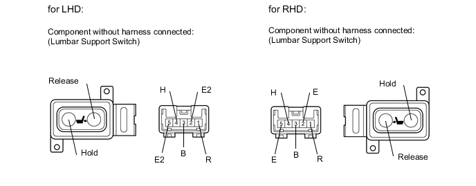
INSPECT LUMBAR SUPPORT SWITCH
-
Remove the lumbar support switch Click here.
-
Measure the resistance according to the value(s) in the table below.
Standard Resistance for LHD Tester Connection Switch Condition Specified Condition 3 (B) - 4 (H) Hold Below 1 Ω 1 (R) - 2 (E2) 4 (H) - 5 (E2) Off 1 (R) - 2 (E2) 4 (H) - 5 (E2) Release 1 (R) - 3 (B) for RHD Tester Connection Switch Condition Specified Condition 3 (B) - 4 (H) Hold Below 1 Ω 1 (R) - 2 (E) 4 (H) - 5 (E) Off 1 (R) - 2 (E) 4 (H) - 5 (E) Release 1 (R) - 3 (B)
NG
REPLACE LUMBAR SUPPORT SWITCH Click here
OK
-
-
INSPECT LUMBAR SUPPORT ADJUSTER ASSEMBLY
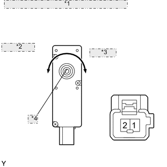
*1 Component without harness connected: (Lumbar Support Adjuster) *2 Counterclockwise *3 Clockwise *4 Driving Axis
-
Remove the lumbar support adjuster Click here.
-
Check operation of the lumbar support adjuster.
-
Check that the lumbar support adjuster moves smoothly when the battery is connected to the lumbar support adjuster motor connector terminals.
OK for LHD Measurement Condition Specified Condition Battery positive (+) → 1
Battery negative (-) → 2
Clockwise Battery positive (+) → 2
Battery negative (-) → 1
Counterclockwise for RHD Measurement Condition Specified Condition Battery positive (+) → 2
Battery negative (-) → 1
Clockwise Battery positive (+) → 1
Battery negative (-) → 2
Counterclockwise
-
NG
REPLACE LUMBAR SUPPORT ADJUSTER ASSEMBLY Click here
OK
-
-
CHECK HARNESS AND CONNECTOR (LUMBAR SUPPORT SWITCH - BATTERY AND BODY GROUND)
-
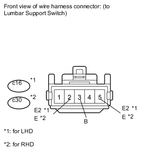
Disconnect the c16*1 or c30*2 lumbar support switch connector.
-
*1: for LHD
-
*2: for RHD
-
-
Measure the voltage according to the value(s) in the table below.
Standard Voltage for LHD Tester Connection Condition Specified Condition c16-3 (B) - Body ground Always 11 to 14 V for RHD Tester Connection Condition Specified Condition c30-3 (B) - Body ground Always 11 to 14 V -
Measure the resistance according to the value(s) in the table below.
Standard Resistance for LHD Tester Connection Condition Specified Condition c16-5 (E2) - Body ground Always Below 1 Ω c16-2 (E2) - Body ground for RHD Tester Connection Condition Specified Condition c30-5 (E) - Body ground Always Below 1 Ω c30-2 (E) - Body ground
OK
REPAIR OR REPLACE HARNESS OR CONNECTOR (LUMBAR SUPPORT SWITCH - LUMBAR SUPPORT ADJUSTER ASSEMBLY)
NG
REPAIR OR REPLACE HARNESS OR CONNECTOR
-
-
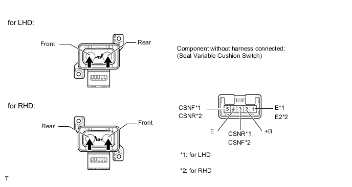
INSPECT SEAT VARIABLE CUSHION SWITCH
-
Remove the seat variable cushion switch Click here.
-
Measure the resistance according to the value(s) in the table below.
Standard Resistance for LHD Tester Connection Switch Condition Specified Condition 2 (+B) - 5 (CSNF) Front Below 1 Ω 3 (CSNR) - 4 (E) 3 (CSNR) - 4 (E) Off 1 (E) - 5 (CSNF) 2 (+B) - 3 (CSNR) Rear 1 (E) - 5 (CSNF) for RHD Tester Connection Switch Condition Specified Condition 2 (+B) - 3 (CSNF) Front Below 1 Ω 5 (CSNR) - 4 (E) 3 (CSNF) - 1 (E2) Off 5 (CSNR) - 4 (E) 2 (+B) - 5 (CSNR) Rear 3 (CSNF) - 1 (E2)
NG
REPLACE SEAT VARIABLE CUSHION SWITCH Click here
OK
-
-
INSPECT FRONT SEAT ASSEMBLY (VARIABLE MOTOR)
-
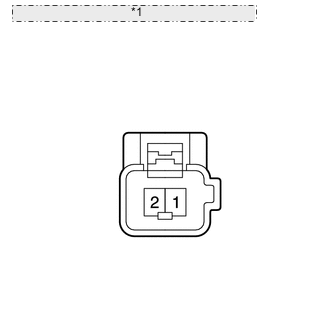
*1 Component without harness connected: (Variable Motor) Remove the front seat with adjuster frame LH (for LHD) Click here.
-
Remove the front seat with adjuster frame RH (for RHD) Click here.
-
Check operation of the variable motor.
-
Check if the seat cushion moves smoothly when the battery is connected to the variable motor connector terminals.
OK for LHD Measurement Condition Specified Condition Battery positive (+) → 1
Battery negative (-) → 2
Forward Battery positive (+) → 2
Battery negative (-) → 1
Rearward for RHD Measurement Condition Specified Condition Battery positive (+) → 2
Battery negative (-) → 1
Forward Battery positive (+) → 1
Battery negative (-) → 2
Rearward Result Result Proceed to OK A NG (for LHD) B NG (for RHD) C
-
B
REPLACE FRONT SEAT WITH ADJUSTER FRAME ASSEMBLY LH Click here
C
REPLACE FRONT SEAT WITH ADJUSTER FRAME ASSEMBLY RH Click here
A
-
-
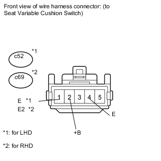
CHECK HARNESS AND CONNECTOR (SEAT VARIABLE CUSHION SWITCH - BATTERY AND BODY GROUND)
-
Disconnect the c52*1 or c69*2 seat variable cushion switch connector.
-
*1: for LHD
-
*2: for RHD
-
-
Measure the voltage according to the value(s) in the table below.
Standard Voltage for LHD Tester Connection Condition Specified Condition c52-2 (+B) - Body ground Always 11 to 14 V for RHD Tester Connection Condition Specified Condition c69-2 (+B) - Body ground Always 11 to 14 V -
Measure the resistance according to the value(s) in the table below.
Standard Resistance for LHD Tester Connection Condition Specified Condition c52-1 (E) - Body ground Always Below 1 Ω c52-4 (E) - Body ground for RHD Tester Connection Condition Specified Condition c69-1 (E2) - Body ground Always Below 1 Ω c69-4 (E) - Body ground
OK
REPAIR OR REPLACE HARNESS OR CONNECTOR (SEAT VARIABLE CUSHION SWITCH - VARIABLE MOTOR)
NG
REPAIR OR REPLACE HARNESS OR CONNECTOR
-