FRONT POWER SEAT CONTROL SYSTEM Front Power Seat does not Operate with Front Power Seat Switch
DESCRIPTION
When a signal is input into the front power seat switch, the ECU receives manages the signals operates each motor. When 2 or more signals are input, the motors only operate when the signals are from the slide switch and reclining switch.
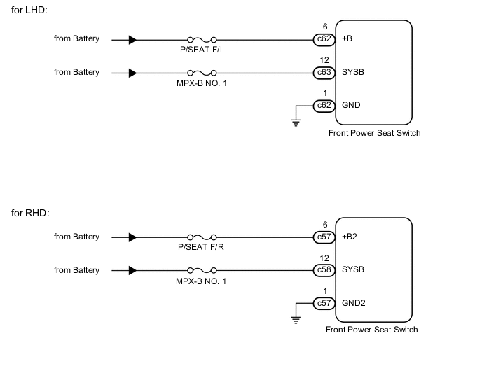
WIRING DIAGRAM
PROCEDURE
-
INSPECT FUSE (P/SEAT F/L, P/SEAT F/R, MPX-B NO. 1)
-
Remove the P/SEAT F/L*1, P/SEAT F/R*2 and MPX-B NO. 1 fuses from the main body ECU (multiplex network body ECU).
-
*1: for LHD
-
*2: for RHD
-
-
Measure the resistance according to the value(s) in the table below.
Standard Resistance for LHD Tester Connection Condition Specified Condition P/SEAT F/L fuse Always Below 1 Ω MPX-B NO. 1 fuse Always Below 1 Ω for RHD Tester Connection Condition Specified Condition P/SEAT F/R fuse Always Below 1 Ω MPX-B NO. 1 fuse Always Below 1 Ω
NG 
REPLACE FUSE
OK 
-
-
CHECK HARNESS AND CONNECTOR (FRONT POWER SEAT SWITCH - BATTERY AND BODY GROUND)
-
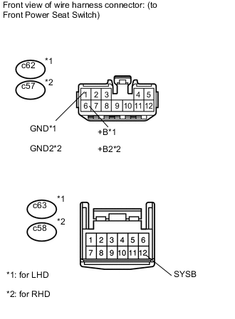
Disconnect the c62*1, c63*1 or c57*2, c58*2 front power seat switch connectors.
-
*1: for LHD
-
*2: for RHD
-
-
Measure the voltage according to the value(s) in the table below.
Standard Voltage for LHD Tester Connection Condition Specified Condition c62-6 (+B) - Body ground Always 11 to 14 V c63-12 (SYSB) - Body ground Always 11 to 14 V for RHD Tester Connection Condition Specified Condition c57-6 (+B2) - Body ground Always 11 to 14 V c58-12 (SYSB) - Body ground Always 11 to 14 V -
Measure the resistance according to the value(s) in the table below.
Standard Resistance for LHD Tester Connection Condition Specified Condition c62-1 (GND) - Body ground Always Below 1 Ω for RHD Tester Connection Condition Specified Condition c57-1 (GND2) - Body ground Always Below 1 Ω
OK
REPLACE FRONT POWER SEAT SWITCH Click here
NG
REPAIR OR REPLACE HARNESS OR CONNECTOR
-