FRONT POWER SEAT CONTROL SYSTEM, Diagnostic DTC:B2650
| DTC Code | DTC Name |
|---|---|
| B2650 | Slide Sensor Malfunction |
DESCRIPTION
When the front power seat switch does not receive a sensor signal despite forward or backward movement of the seat by power seat motor operation, this DTC is stored.
| DTC Code | DTC Detection Condition | Trouble Area |
|---|---|---|
| B2650 | The forward and backward lock detection position of the sensor is the same. |
|
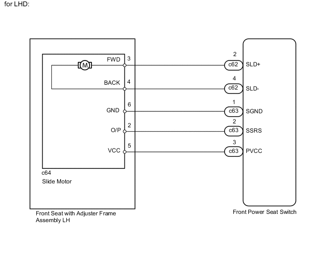
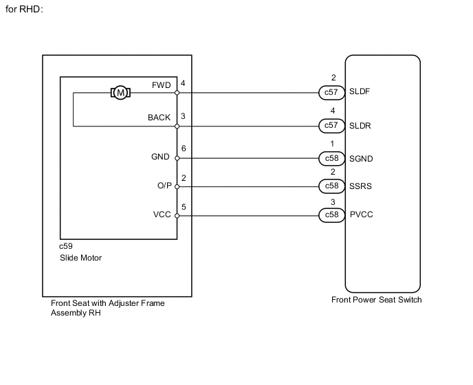
WIRING DIAGRAM
PROCEDURE
-
PERFORM ACTIVE TEST USING GTS (POWER SEAT MOTOR FUNCTION)
-
Select the Active Test, use the GTS to generate a control command, and then check the power seat motor function Click here.
Driver Seat Tester Display Test Part Control Range Diagnostic Note Seat Slide Operation Seat sliding operation Front / OFF / Rear - OK Motor operates normally.
NG 
INSPECT FRONT SEAT WITH ADJUSTER FRAME ASSEMBLY (SLIDE MOTOR) Click here
OK 
-
-
CHECK FRONT POWER SEAT SWITCH (SLIDE MOTOR CIRCUIT)
-
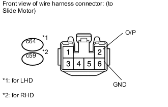
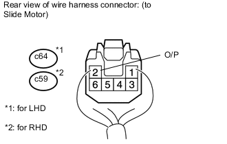
Disconnect the c64*1 or C59*2 slide motor connector.
-
*1: for LHD
-
*2: for RHD
-
-
Measure the voltage according to the value(s) in the table below.
Standard Voltage for LHD Tester Connection Switch Condition Specified Condition c64-2 (O/P) - c64-6 (GND) Sliding switch on 4.8 to 5.1 V for RHD Tester Connection Switch Condition Specified Condition c59-2 (O/P) - c59-6 (GND) Sliding switch on 4.8 to 5.1 V
NG
CHECK HARNESS AND CONNECTOR (FRONT POWER SEAT SWITCH - SLIDE MOTOR) Click here
OK
-
-
CHECK FRONT SEAT WITH ADJUSTER FRAME ASSEMBLY (SLIDE MOTOR)
-
Connect the c64*1 or c59*2 slide motor connector.
-
*1: for LHD
-
*2: for RHD
-
-
Measure the voltage according to the value(s) in the table below.
Standard Voltage for LHD Tester Connection Switch Condition Specified Condition c64-2 (O/P) - Body ground Sliding switch on 4.5 to 4.8 V for RHD Tester Connection Switch Condition Specified Condition c59-2 (O/P) - Body ground Sliding switch on 4.5 to 4.8 V Result Result Proceed to OK A NG (for LHD) B NG (for RHD) C
A 
REPLACE FRONT POWER SEAT SWITCH Click here
B
REPLACE FRONT SEAT WITH ADJUSTER FRAME ASSEMBLY LH Click here
C
REPLACE FRONT SEAT WITH ADJUSTER FRAME ASSEMBLY RH Click here
-
-
CHECK HARNESS AND CONNECTOR (FRONT POWER SEAT SWITCH - SLIDE MOTOR)
-
*1: for LHD
-
*2: for RHD
-
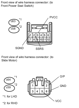
Disconnect the c63*1 or c58*2 front power seat switch connector.
-
Disconnect the c64*1 or C59*2 slide motor connector.
-
Measure the resistance according to the value(s) in the table below.
Standard Resistance for LHD Tester Connection Condition Specified Condition c63-2 (SSRS) - c64-2 (O/P) Always Below 1 Ω c63-1 (SGND) - c64-6 (GND) Always Below 1 Ω c63-3 (PVCC) - c64-5 (VCC) Always Below 1 Ω c63-1 (SGND) - Body ground Always 10 kΩ or higher c63-2 (SSRS) - Body ground Always 10 kΩ or higher c63-3 (PVCC) - Body ground Always 10 kΩ or higher for RHD Tester Connection Condition Specified Condition c58-2 (SSRS) - c59-2 (O/P) Always Below 1 Ω c58-1 (SGND) - c59-6 (GND) Always Below 1 Ω c58-3 (PVCC) - c59-5 (VCC) Always Below 1 Ω c58-1 (SGND) - Body ground Always 10 kΩ or higher c58-2 (SSRS) - Body ground Always 10 kΩ or higher c58-3 (PVCC) - Body ground Always 10 kΩ or higher
OK
REPLACE FRONT POWER SEAT SWITCH Click here
NG
REPAIR OR REPLACE HARNESS OR CONNECTOR
-
-
INSPECT FRONT SEAT WITH ADJUSTER FRAME ASSEMBLY (SLIDE MOTOR)
-
Remove the front seat with adjuster frame assembly (slide motor) Click here.
-
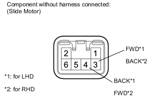
Check if the seat cushion spring moves smoothly when the battery is connected to the slide motor connector terminals.
OK for LHD Measurement Condition Specified Condition Battery positive (+) → 3 (FWD)
Battery negative (-) → 4 (BACK)
Seat cushion spring moves forward Battery positive (+) → 4 (BACK)
Battery negative (-) → 3 (FWD)
Seat cushion spring moves backward for RHD Measurement Condition Specified Condition Battery positive (+) → 4 (FWD)
Battery negative (-) → 3 (BACK)
Seat cushion spring moves forward Battery positive (+) → 3 (BACK)
Battery negative (-) → 4 (FWD)
Seat cushion spring moves backward Result Result Proceed to OK A NG (for LHD) B NG (for RHD) C
B
REPLACE FRONT SEAT WITH ADJUSTER FRAME ASSEMBLY LH Click here
C
REPLACE FRONT SEAT WITH ADJUSTER FRAME ASSEMBLY RH Click here
A
-
-
CHECK HARNESS AND CONNECTOR (FRONT POWER SEAT SWITCH - SLIDE MOTOR)
-
*1: for LHD
-
*2: for RHD
-
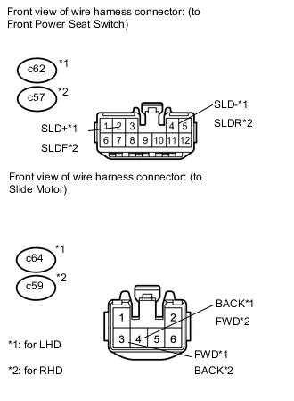
Disconnect the c62*1 or c57*2 front power seat switch connector.
-
Disconnect the c64*1 or c59*2 slide motor connector.
-
Measure the resistance according to the value(s) in the table below.
Standard Resistance for LHD Tester Connection Condition Specified Condition c62-2 (SLD+) - c64-3 (FWD) Always Below 1 Ω c62-4 (SLD-) - c64-4 (BACK) Always Below 1 Ω c62-2 (SLD+) - Body ground Always 10 kΩ or higher c62-4 (SLD-) - Body ground Always 10 kΩ or higher for RHD Tester Connection Condition Specified Condition c57-2 (SLDF) - c59-4 (FWD) Always Below 1 Ω c57-4 (SLDR) - c59-3 (BACK) Always Below 1 Ω c57-2 (SLDF) - Body ground Always 10 kΩ or higher c57-4 (SLDR) - Body ground Always 10 kΩ or higher
OK
REPLACE FRONT POWER SEAT SWITCH Click here
NG
REPAIR OR REPLACE HARNESS OR CONNECTOR
-