PRE-CRASH SAFETY SYSTEM, Diagnostic DTC:C1A4B
| DTC Code | DTC Name |
|---|---|
| C1A4B | Stop Light Relay Circuit |
DESCRIPTION
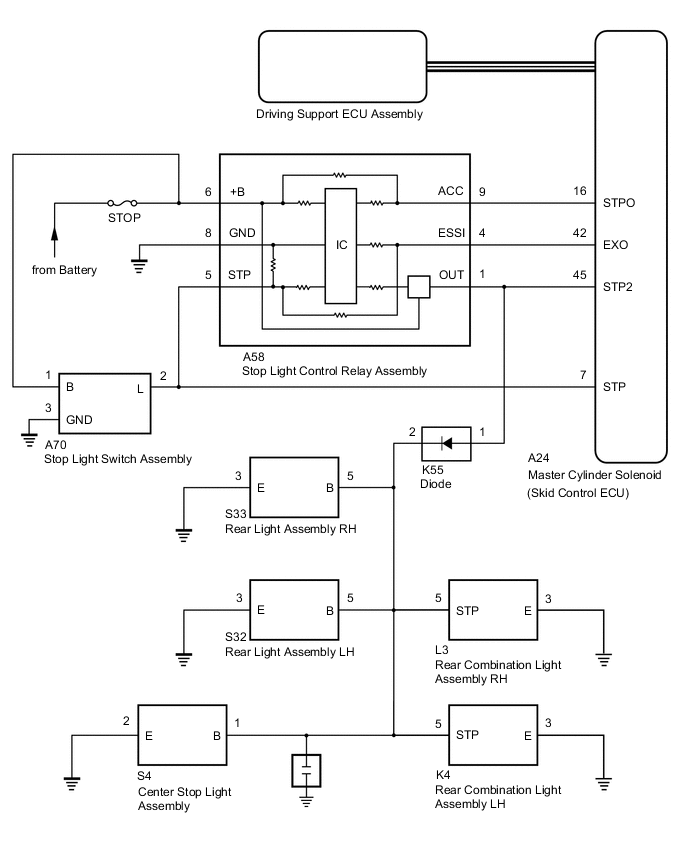
The master cylinder solenoid (skid control ECU) sends a stop light operation request signal to the stop light control relay assembly. If the master cylinder solenoid (skid control ECU) detects a malfunction in the stop light relay circuit, the driving support ECU assembly stores DTC C1A4B.
| Vehicle Condition | |||
|---|---|---|---|
| Pattern 1 | Pattern 2 | ||
| Diagnosis Condition | IG1 terminal voltage is 11 to 14 V | ○ | ○ |
| Stop Light illumination output (STPO) ON | ○ | - | |
| Stop Light illumination output (STPO) OFF | - | ○ | |
| Malfunction Status | No signal input to STP2 terminal | ○ | - |
| Signals input to STP and STP2 terminals do not match | - | ○ | |
| Malfunction Time | 0.3 seconds or more | 0.3 seconds or more | |
| Number of Trips | - | - | |
| DTC No. | DTC Detection Condition | Trouble Area |
|---|---|---|
| C1A4B | Either of the following conditions is met:
|
|
WIRING DIAGRAM
CAUTION / NOTICE / HINT
Note
-
Inspect the fuses for circuits related to this system before performing the following procedure.
-
After replacing the master cylinder solenoid, perform zero point calibration and store the system information Click here.
-
When the start function does not operate, check the Entry and Start System (for start function) Click here.
PROCEDURE
-
CHECK STOP LIGHT OPERATION
-
Check that the stop lights come on when the brake pedal is depressed and go off when the brake pedal is released.
OK: Condition Illumination Condition Brake pedal depressed On Brake pedal released Off
NG 
GO TO LIGHTING SYSTEM Click here
OK 
-
-
CHECK HARNESS AND CONNECTOR (STPO TERMINAL VOLTAGE)
-
Turn the engine switch off.
-
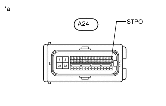
Text in Illustration *a Front view of wire harness connector (to Master Cylinder Solenoid [Skid Control ECU]) Disconnect the master cylinder solenoid (skid control ECU) connector.
-
Measure the voltage according to the value(s) in the table below.
Standard Voltage Tester Connection Condition Specified Condition A24-16 (STPO) - Body ground Engine switch on (IG) 11 to 14 V
NG 
CHECK HARNESS AND CONNECTOR (STOP LIGHT CONTROL RELAY ASSEMBLY - MASTER CYLINDER SOLENOID [SKID CONTROL ECU]) Click here
OK
-
-
PERFORM ACTIVE TEST USING ACTIVE TEST USING GTS (STOP LIGHT RELAY)
-
Enter the following menus: Chassis / ABS/VSC/TRAC / Active Test.
-
Perform "Active Test" according to the display on the GTS.
ABS/VSC/TRAC Tester Display Test Part Control Range Diagnostic Note Stop Light Relay Stop lights ON / OFF Test possible at vehicle speed of 0 km/h (0 mph) -
Enter the following menus: Chassis / ABS/VSC/TRAC / Data List.
-
Check the stop light switch assembly (stop light control relay assembly) operation using the Data List and stop light operation by performing an Active Test.
ABS/VSC/TRAC Tester Display Measurement Item/Range Normal Condition Diagnostic Note Stop Light Relay Output STOP terminal output condition/ON or OFF ON: Output
OFF: Not output
- Result Result Proceed to When Active Test performed, Data List item not changes between ON and OFF A When Active Test performed, Data List item changes between ON and OFF and stop lights turn on and off B
B
CHECK HARNESS AND CONNECTOR (STP2 TERMINAL VOLTAGE) Click here
A
-
-
INSPECT MASTER CYLINDER SOLENOID (SKID CONTROL ECU)
-
Enter the following menus: Chassis / ABS/VSC/TRAC / Active Test.
-
Perform "Active Test" according to the display on the GTS.
ABS/VSC/TRAC Tester Display Test Part Control Range Diagnostic Note Stop Light Relay Stop lights ON / OFF Test possible at vehicle speed of 0 km/h (0 mph) -
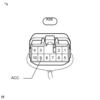
Text in Illustration *a Component with harness connected
(Stop Light Control Relay Assembly)
Measure the voltage according to the value(s) in the table below.
Standard Voltage Tester Connection Condition Specified Condition A58-9 (ACC) - Body ground Active test is ON Below 1.5 V Result Result Proceed to OK A NG (for LHD) B NG (for RHD) C
B
REPLACE MASTER CYLINDER SOLENOID (SKID CONTROL ECU) Click here
C
REPLACE MASTER CYLINDER SOLENOID (SKID CONTROL ECU) Click here
A
-
-
REPLACE STOP LIGHT CONTROL RELAY ASSEMBLY
-
Replace the stop light control relay assembly.
for LHD: Click here
for RHD: Click here
NEXT
-
-
CHECK FOR DTC
-
Enter the following menus: Chassis / ABS/VSC/TRAC / Active Test.
Tech Tips
If the detection conditions are not met, the system cannot detect the malfunction.
-
Using the GTS, perform the Active Test "Stop Light Relay" with the ignition switch to ON.
-
-
Perform "Active Test" according to the display on the GTS.
Tester Display Test Part Control Range Diagnostic Note Stop Light Relay Stop lights ON / OFF Test possible at vehicle speed of 0 km/h (0 mph) EBS Relay Stop light control relay
(Emergency brake signal)
ON / OFF - -
Enter the following menus: Chassis / ABS/VSC/TRAC / Data List.
-
Check the stop light switch assembly (stop light control relay assembly) operation using the Data List and stop light operation by performing an Active Test.
Tester Display Measurement Item/Range Normal Condition Diagnostic Note Stop Light Relay Output STOP terminal output condition/ON or OFF ON: Output
ON: Not output
- EBS Relay Stop light control relay (Emergency brake signal)/ON or OFF ON: Relay on
OFF: Relay off
- -
Clear the DTCs Click here.
-
Check for DTCs Click here.
Result Result Proceed to DTC C1380 is output A DTC C1380 is not output B
A
GO TO DTC C1380 Click here
B
END (STOP LIGHT CONTROL RELAY ASSEMBLY WAS DEFECTIVE)
-
-
CHECK HARNESS AND CONNECTOR (STP2 TERMINAL VOLTAGE)
-
Turn the engine switch off.
-
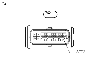
Text in Illustration *a Front view of wire harness connector
(to Master Cylinder Solenoid [Skid Control ECU])
Disconnect the master cylinder solenoid (skid control ECU) connector.
-
Measure the voltage according to the value(s) in the table below.
Standard Voltage Tester Connection Condition Specified Condition A24-45 (STP2) - Body ground Brake pedal depressed 11 to 14 V
NG
REPAIR OR REPLACE HARNESS OR CONNECTOR
OK
-
-
REPLACE MASTER CYLINDER SOLENOID (SKID CONTROL ECU)
-
Replace the master cylinder solenoid (skid control ECU).
for LHD: Click here
for RHD: Click here
NEXT
-
-
CHECK FOR DTC
-
Enter the following menus: Chassis / ABS/VSC/TRAC / Active Test.
Tech Tips
If the detection conditions are not met, the system cannot detect the malfunction.
-
Using the GTS, perform the Active Test "Stop Light Relay" with the ignition switch to ON.
-
-
Perform "Active Test" according to the display on the GTS.
Tester Display Test Part Control Range Diagnostic Note Stop Light Relay Stop lights ON / OFF Test possible at vehicle speed of 0 km/h (0 mph) EBS Relay Stop light control relay
(Emergency brake signal)
ON / OFF - -
Enter the following menus: Chassis / ABS/VSC/TRAC / Data List.
-
Check the stop light switch assembly (stop light control relay assembly) operation using the Data List and stop light operation by performing an Active Test.
Tester Display Measurement Item/Range Normal Condition Diagnostic Note Stop Light Relay Output STOP terminal output condition/ON or OFF ON: Output
ON: Not output
- EBS Relay Stop light control relay (Emergency brake signal)/ON or OFF ON: Relay on
OFF: Relay off
- -
Clear the DTCs Click here.
-
Check for DTCs Click here.
Result Result Proceed to DTC C1380 is output A DTC C1380 is not output B
A
GO TO DTC C1380 Click here
B
END (STOP LIGHT CONTROL RELAY ASSEMBLY WAS DEFECTIVE)
-
-
CHECK HARNESS AND CONNECTOR (STOP LIGHT CONTROL RELAY ASSEMBLY - MASTER CYLINDER SOLENOID [SKID CONTROL ECU])
-
Disconnect the A58 stop light control relay assembly connector.
-
Disconnect the A24 master cylinder solenoid (skid control ECU) connector.
-
Measure the resistance according to the value(s) in the table below.
Standard Resistance Tester Connection Condition Specified Condition A58-9 (ACC) - A24-16 (STPO) Always Below 1 Ω A58-9 (ACC) or A24-16 (STPO) - Body ground Always 10 kΩ or higher
NG
REPAIR OR REPLACE HARNESS OR CONNECTOR
OK
-
-
REPLACE STOP LIGHT CONTROL RELAY ASSEMBLY
-
Replace the stop light control relay assembly.
for LHD: Click here
for RHD: Click here
NEXT
-
-
CHECK FOR DTC
-
Enter the following menus: Chassis / ABS/VSC/TRAC / Active Test.
Tech Tips
If the detection conditions are not met, the system cannot detect the malfunction.
-
Using the GTS, perform the Active Test "Stop Light Relay" with the ignition switch to ON.
-
-
Perform "Active Test" according to the display on the GTS.
Tester Display Test Part Control Range Diagnostic Note Stop Light Relay Stop lights ON / OFF Test possible at vehicle speed of 0 km/h (0 mph) EBS Relay Stop light control relay
(Emergency brake signal)
ON / OFF - -
Enter the following menus: Chassis / ABS/VSC/TRAC / Data List.
-
Check the stop light switch assembly (stop light control relay assembly) operation using the Data List and stop light operation by performing an Active Test.
Tester Display Measurement Item/Range Normal Condition Diagnostic Note Stop Light Relay Output STOP terminal output condition/ON or OFF ON: Output
ON: Not output
- EBS Relay Stop light control relay (Emergency brake signal)/ON or OFF ON: Relay on
OFF: Relay off
- -
Clear the DTCs Click here.
-
Check for DTCs Click here.
Result Result Proceed to DTC C1380 is output A DTC C1380 is not output B
A
GO TO DTC C1380 Click here
B
END (STOP LIGHT CONTROL RELAY ASSEMBLY WAS DEFECTIVE)
-