HEADUP DISPLAY SWITCH INSPECTION
PROCEDURE
-
INSPECT COMBINATION SWITCH ASSEMBLY (HEADUP DISPLAY SWITCH) (for LHD)
-
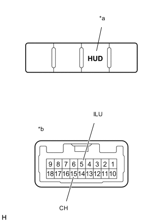
Text in Illustration *a HUD Switch *b Component without harness connected
(Combination Switch Assembly (Headup Display Switch))
Check the resistance.
Measure the resistance according to the value(s) in the table below.
Standard Resistance Tester Connection Switch Condition Specified Condition 5 (ILU) - 15 (CH) HUD switch on (Pushed) Below 1 Ω HUD switch off (Not pushed) 10 kΩ or higher If the result is not as specified, replace the combination switch assembly (headup display switch).
-
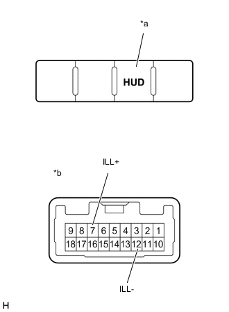
Text in Illustration *a Illuminates *b Component without harness connected
(Combination Switch Assembly (Headup Display Switch))
Check the illumination.
Apply battery voltage to the connector and check the illumination condition.
OK Measurement Condition Specified Condition Battery positive (+) → Terminal 7 (ILL+)
Battery negative (-) → Terminal 12 (ILL-)
Illuminates If the result is not as specified, replace the combination switch assembly (headup display switch).
-
-
INSPECT COMBINATION SWITCH ASSEMBLY (HEADUP DISPLAY SWITCH) (for RHD)
-
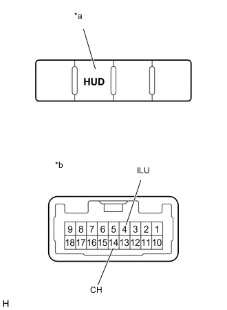
Text in Illustration *a HUD Switch *b Component without harness connected
(Combination Switch Assembly (Headup Display Switch))
Check the resistance.
Measure the resistance according to the value(s) in the table below.
Standard Resistance Tester Connection Switch Condition Specified Condition 4 (ILU) - 14 (CH) HUD switch on (Pushed) Below 1 Ω HUD switch off (Not pushed) 10 kΩ or higher If the result is not as specified, replace the combination switch assembly (headup display switch).
-
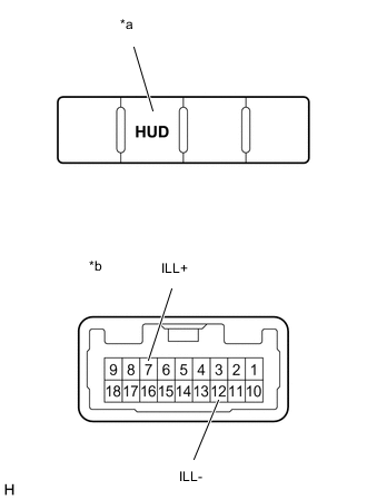
Text in Illustration *a Illuminates *b Component without harness connected
(Combination Switch Assembly (Headup Display Switch))
Check the illumination.
Apply battery voltage to the connector and check the illumination condition.
OK Measurement Condition Specified Condition Battery positive (+) → Terminal 7 (ILL+)
Battery negative (-) → Terminal 12 (ILL-)
Illuminates If the result is not as specified, replace the combination switch assembly (headup display switch).
-