HEADUP DISPLAY SYSTEM SYSTEM DESCRIPTION
-
Outline of Headup Display System
-
The headup display system is connected to CAN communication and local bus communication, receives signals from each ECU and displays each screen.
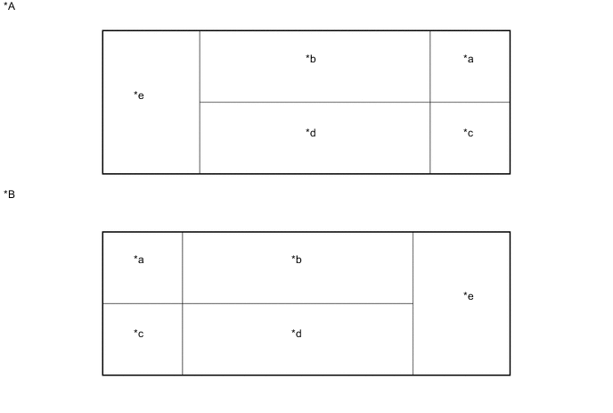
Text in Illustration *A for LHD *B for RHD *a Display Area A *b Display Area B *c Display Area C *d Display Area D *e Display Area E - - Area Order of Priority Display Details A 1 Master Warning Lamp 2 Information B 1 PCS Warning Display*1 2 Audio information 3 Radar Cruise Control Information*4 4 Speed Limit Animation (Road Sign Assist*3/Navigation Information) 5 Ambient Temperature/Road Surface Ice Display C - Speed Meter 1 Speed Limit (Road Sign Assist)*3 2 Speed Limit (Navigation Information) Road Sign Assistant Information*3 D 1 Radar Cruise Control Warning Message*4 Lane-keeping Assist System Deviation Warning*5 2 Clearance Sonar Detection Display (Farthest, Far, Medium and Near Distances)*6 5 Radar Cruise Control Normal Screen (Notifications for Conditions Other than Proximity Warnings)*1 6 Radar Cruise Control Normal Screen (Vehicle-to-vehicle Communication Condition)*4 E 1 Navigation System (Turn-by-turn, Intersection Name and Next Street Name) 2 Compass
-
*1: w/ Pre-crash Safety System
-
*2: w/ LEXUS Parking Assist-sensor System
-
*3: w/ Road Sign Assist System
-
*4: w/ Dynamic Radar Cruise Control System
-
*5: w/ Lane Departure Alert System
-
-