METER / GAUGE SYSTEM, Diagnostic DTC:B1507, B1508
| DTC Code | DTC Name |
|---|---|
| B1507 | Open in Turn Signal Circuit |
| B1508 | Short in Turn Signal / Hazard Flasher Circuit |
DESCRIPTION
| DTC Code | DTC Detection Condition | Trouble Area |
|---|---|---|
| B1507 | Both conditions are met:
|
|
| B1508 | Both conditions are met:
|
|
WIRING DIAGRAM
-
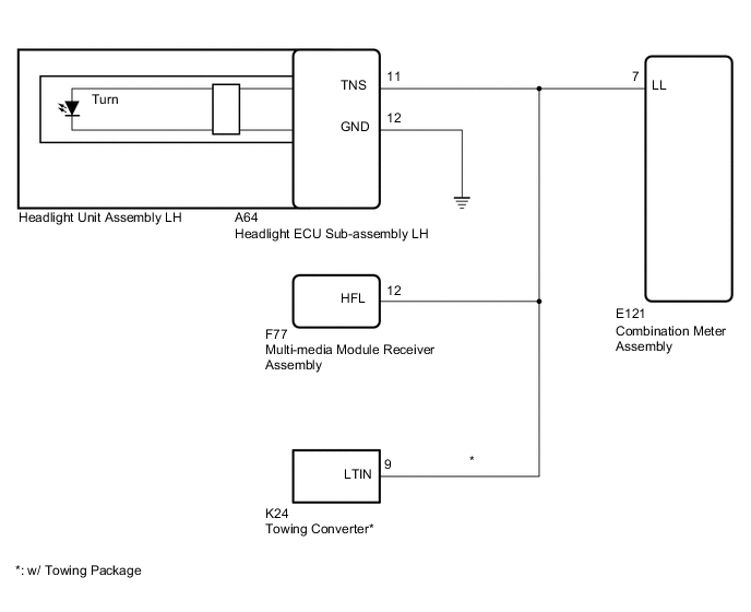
Front LH Side:
-
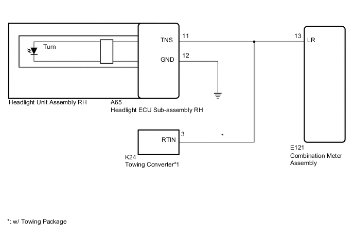
Front RH Side:
-
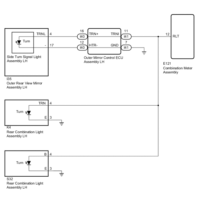
Rear LH Side:
-
Rear RH Side:

CAUTION / NOTICE / HINT
Note
Inspect the bulbs for circuits related to this system before performing the following inspection procedure.
PROCEDURE
-
CHECK FOR DTC
-
Clear the DTCs Click here.
-
Recheck for DTCs and check that no DTCs are output Click here.
OK B1507 and B1508 are not output. Result Proceed to NG A OK B
B 
USE SIMULATION METHOD TO CHECK Click here
A 
-
-
CHECK TURN SIGNAL LIGHT
-
Check the illumination of each turn signal light.
Result Result Proceed to LH side front turn signal light does not illuminate. A RH side front turn signal light does not illuminate. B LH side rear or side turn signal light does not illuminate. C RH side rear or side turn signal light does not illuminate. D
B 
CHECK HARNESS AND CONNECTOR (RH SIDE CIRCUIT) Click here
C
CHECK HARNESS AND CONNECTOR (LH SIDE CIRCUIT) Click here
D
CHECK HARNESS AND CONNECTOR (RH SIDE CIRCUIT) Click here
A
-
-
CHECK HARNESS AND CONNECTOR (LH SIDE CIRCUIT)
-
*: w/ Towing Package
-
Disconnect the E121 combination meter assembly connector.
-
Disconnect the A64 headlight ECU assembly LH connector.
-
Disconnect the F77 multi-media module receiver assembly connector.
-
Disconnect the K24 towing converter connector.*
-
Measure the resistance according to the value(s) in the table below.
Standard Resistance Tester Connection Condition Specified Condition E121-7 (LL) - A64-11 (TNS) Always Below 1 Ω E121-7 (LL) - F77-12 (HFL) Always Below 1 Ω A64-12 (GND) - Body ground Always Below 1 Ω E121-7 (LL) - K24-9 (LTIN) Always Below 1 Ω E121-7 (LL) - Body ground Always 10 kΩ or higher
NG
REPAIR OR REPLACE HARNESS OR CONNECTOR
OK
-
-
CHECK HEADLIGHT ECU SUB-ASSEMBLY LH
-
Replace the headlight ECU sub-assembly LH Click here.
-
Clear the DTCs Click here.
-
Recheck for DTCs and check that no DTCs are output Click here.
OK B1507 and B1508 are not output. Result Proceed to NG A OK B
B
END (HEADLIGHT ECU SUB-ASSEMBLY LH IS DEFECTIVE)
A
-
-
CHECK HEADLIGHT UNIT ASSEMBLY LH
-
Replace the headlight unit assembly LH Click here.
-
Clear the DTCs Click here.
-
Recheck for DTCs and check that no DTCs are output Click here.
OK B1507 and B1508 are not output.
OK
END (HEADLIGHT UNIT ASSEMBLY LH IS DEFECTIVE)
NG
REPLACE COMBINATION METER ASSEMBLY Click here
-
-
CHECK HARNESS AND CONNECTOR (RH SIDE CIRCUIT)
-
*: w/ Towing Package
-
Disconnect the E121 combination meter assembly connector.
-
Disconnect the A65 headlight ECU assembly RH connector.
-
Disconnect the K24 towing converter connector.*
-
Measure the resistance according to the value(s) in the table below.
Standard Resistance Tester Connection Condition Specified Condition E121-13 (LR) - A65-11 (TNS) Always Below 1 Ω A65-12 (GND) - Body ground Always Below 1 Ω E121-13 (LR)- K24-3 (RTIN) Always Below 1 Ω E121-13 (LR) - Body ground Always 10 kΩ or higher
NG
REPAIR OR REPLACE HARNESS OR CONNECTOR
OK
-
-
CHECK HEADLIGHT ECU SUB-ASSEMBLY RH
-
Replace the headlight ECU sub-assembly RH Click here.
-
Clear the DTCs Click here.
-
Recheck for DTCs and check that no DTCs are output Click here.
OK B1507 and B1508 are not output. Result Proceed to NG A OK B
B
END (HEADLIGHT ECU SUB-ASSEMBLY RH IS DEFECTIVE)
A
-
-
CHECK HEADLIGHT UNIT ASSEMBLY RH
-
Replace the headlight unit assembly RH Click here.
-
Clear the DTCs Click here.
-
Recheck for DTCs and check that no DTCs are output Click here.
OK B1507 and B1508 are not output.
OK
END (HEADLIGHT UNIT ASSEMBLY RH IS DEFECTIVE)
NG
REPLACE COMBINATION METER ASSEMBLY Click here
-
-
CHECK HARNESS AND CONNECTOR (LH SIDE CIRCUIT)
-
Disconnect the E121 combination meter assembly connector.
-
Disconnect the I35 outer rear view mirror assembly LH connector.
-
Disconnect the K4 rear combination light assembly LH connector.
-
Disconnect the S32 rear combination light assembly LH connector.
-
Measure the resistance according to the value(s) in the table below.
Standard Resistance Tester Connection Condition Specified Condition E121-12 (RLT) - I35-4 (TRNR) Always Below 1 Ω E121-12 (RLT) - K4-4 (TRN) Always Below 1 Ω E121-12 (RLT) - S32-4 (B) Always Below 1 Ω I35-17 (-) - Body ground Always Below 1 Ω K4-3 (E) - Body ground Always Below 1 Ω S32-3 (E) - Body ground Always Below 1 Ω E121-12 (RLT) - Body ground Always 10 kΩ or higher
NG
CHECK HARNESS AND CONNECTOR (LH SIDE CIRCUIT) Click here
OK
-
-
CHECK OUTER REAR VIEW MIRROR ASSEMBLY LH
-
Remove the outer rear view mirror assembly LH Click here.
-
Inspect the outer rear view mirror assembly LH Click here.
NG
REPLACE OUTER REAR VIEW MIRROR ASSEMBLY LH Click here
OK
-
-
INSPECT SIDE TURN SIGNAL LIGHT ASSEMBLY LH
-
Replace the side turn signal light assembly LH Click here.
-
Inspect the side turn signal light assembly LH Click here.
NG
REPLACE SIDE TURN SIGNAL LIGHT ASSEMBLY LH Click here
OK
-
-
INSPECT REAR COMBINATION LIGHT ASSEMBLY LH
-
Remove the rear combination light assembly LH Click here.
-
Inspect the rear combination light assembly LH Click here.
NG
REPLACE REAR COMBINATION LAMP ASSEMBLY LH Click here
OK
-
-
INSPECT REAR COMBINATION LIGHT ASSEMBLY LH (for Back Door)
-
Remove the rear combination light assembly LH Click here.
-
Inspect the rear combination light assembly LH Click here.
OK
REPLACE COMBINATION METER ASSEMBLY Click here
NG
REPLACE REAR COMBINATION LAMP ASSEMBLY LH Click here
-
-
CHECK HARNESS AND CONNECTOR (LH SIDE CIRCUIT)
-
Disconnect the E121 combination meter assembly connector.
-
Disconnect the I41 outer mirror control ECU assembly LH connector.
-
Disconnect the K4 rear combination light assembly LH connector.
-
Disconnect the S32 rear combination light assembly LH connector.
-
Measure the resistance according to the value(s) in the table below.
Standard Resistance Tester Connection Condition Specified Condition E121-12 (RLT) - I41-11 (TRNI) Always Below 1 Ω E121-12 (RLT) - K4-4 (TRN) Always Below 1 Ω E121-12 (RLT) - S32-4 (B) Always Below 1 Ω I41-7 (GND) - Body ground Always Below 1 Ω K4-3 (E) - Body ground Always Below 1 Ω S32-3 (E) - Body ground Always Below 1 Ω E121-12 (RLT) - Body ground Always 10 kΩ or higher
NG
REPAIR OR REPLACE HARNESS OR CONNECTOR
OK
-
-
CHECK HARNESS AND CONNECTOR (OUTER MIRROR CONTROL ECU ASSEMBLY LH - OUTER REAR VIEW MIRROR ASSEMBLY LH)
-
Disconnect the I40 outer mirror control ECU assembly LH connector.
-
Disconnect the I35 outer rear view mirror assembly LH connector.
-
Measure the resistance according to the value(s) in the table below.
Standard Resistance Tester Connection Condition Specified Condition I40-16 (TRN+) - I35-4 (TRNL) Always Below 1 Ω I40-12 (HTR-) - I35-17 (-) Always Below 1 Ω I40-16 (TRN+) or I35-4 (TRNL) - I40-12 (HTR-) or I35-17 (-) Always 10 kΩ or higher
OK
REPLACE OUTER MIRROR CONTROL ECU ASSEMBLY LH Click here
NG
REPAIR OR REPLACE HARNESS OR CONNECTOR
-
-
CHECK HARNESS AND CONNECTOR (RH SIDE CIRCUIT)
-
Disconnect the E121 combination meter assembly connector.
-
Disconnect the I33 outer rear view mirror assembly RH connector.
-
Disconnect the L3 rear combination light assembly RH connector.
-
Disconnect the S33 rear combination light assembly RH connector.
-
Measure the resistance according to the value(s) in the table below.
Standard Resistance Tester Connection Condition Specified Condition E121-8 (RRT) - I33-4 (TRNR) Always Below 1 Ω E121-8 (RRT) - L3-4 (TRN) Always Below 1 Ω E121-8 (RRT) - S33-4 (B) Always Below 1 Ω I33-17 (-) - Body ground Always Below 1 Ω L3-3 (E) - Body ground Always Below 1 Ω S33-3 (E) - Body ground Always Below 1 Ω E121-8 (RRT) - Body ground Always 10 kΩ or higher
NG
CHECK HARNESS AND CONNECTOR (RH SIDE CIRCUIT) Click here
OK
-
-
INSPECT OUTER REAR VIEW MIRROR ASSEMBLY RH
-
Remove the outer rear view mirror assembly RH Click here.
-
Inspect the outer rear view mirror assembly RH Click here.
NG
REPLACE OUTER REAR VIEW MIRROR ASSEMBLY RH Click here
OK
-
-
INSPECT SIDE TURN SIGNAL LIGHT ASSEMBLY RH
-
Remove the side turn signal light assembly RH Click here.
-
Inspect the side turn signal light assembly RH Click here.
NG
REPLACE SIDE TURN SIGNAL LIGHT ASSEMBLY RH Click here
OK
-
-
INSPECT REAR COMBINATION LIGHT ASSEMBLY RH
-
Remove the rear combination light assembly RH Click here.
-
Inspect the rear combination light assembly RH Click here.
NG
REPLACE REAR COMBINATION LAMP ASSEMBLY RH Click here
OK
-
-
INSPECT REAR COMBINATION LIGHT ASSEMBLY RH (for Back Door)
-
Remove the rear combination light assembly RH Click here.
-
Inspect the rear combination light assembly RH Click here.
OK
REPLACE COMBINATION METER ASSEMBLY Click here
NG
REPLACE REAR COMBINATION LAMP ASSEMBLY RH Click here
-
-
CHECK HARNESS AND CONNECTOR (RH SIDE CIRCUIT)
-
Disconnect the E121 combination meter assembly connector.
-
Disconnect the I38 outer mirror control ECU assembly RH connector.
-
Disconnect the L3 rear combination light assembly RH connector.
-
Disconnect the S33 rear combination light assembly RH connector.
-
Measure the resistance according to the value(s) in the table below.
Standard Resistance Tester Connection Condition Specified Condition E121-8 (RRT) - I38-11 (TRNI) Always Below 1 Ω E121-8 (RRT) - L3-4 (TRN) Always Below 1 Ω E121-8 (RRT) - S33-4 (B) Always Below 1 Ω I38-7 (GND) - Body ground Always Below 1 Ω L3-3 (E) - Body ground Always Below 1 Ω S33-3 (E) - Body ground Always Below 1 Ω E121-8 (RRT) - Body ground Always 10 kΩ or higher
NG
REPAIR OR REPLACE HARNESS OR CONNECTOR
OK
-
-
CHECK HARNESS AND CONNECTOR (OUTER MIRROR CONTROL ECU ASSEMBLY RH - OUTER REAR VIEW MIRROR ASSEMBLY RH)
-
Disconnect the I33 outer rear view mirror assembly RH connector.
-
Disconnect the I37 outer mirror control ECU assembly RH connector.
-
Measure the resistance according to the value(s) in the table below.
Standard Resistance Tester Connection Condition Specified Condition I37-16 (TRN+) - I33-4 (TRNR) Always Below 1 Ω I37-12 (HTR-) - I33-17 (-) Always Below 1 Ω I37-16 (TRN+) or I33-4 (TRNR) - I37-12 (HTR-) or I33-17 (-) Always 10 kΩ or higher
OK
REPLACE OUTER MIRROR CONTROL ECU ASSEMBLY RH Click here
NG
REPAIR OR REPLACE HARNESS OR CONNECTOR
-