METER / GAUGE SYSTEM Fuel Receiver Gauge Malfunction
DESCRIPTION
The fuel sender gauge has a variable resistance mechanism. The resistance decreases when the fuel amount increases, and the resistance increases when the fuel amount decreases. The fuel receiver gauge changes based on the resistance of the fuel sender gauge.
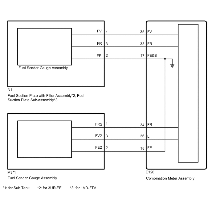
WIRING DIAGRAM
PROCEDURE
-
CHECK FOR DTC
-
Check for DTCs Click here.
Result Result Proceed to DTC B1500 or B1501 is not output A DTC B1500 is output B DTC B1501 is output C
B 
GO TO DTC B1500 Click here
C
GO TO DTC B1501 Click here
A 
-
-
PERFORM ACTIVE TEST USING GTS (FUEL RECEIVER GAUGE ASSEMBLY)
-
Operate the GTS according to the display and select Active Test Click here.
Combination Meter Tester Display Test Part Control Range Diagnostic Note Fuel Meter Operation Fuel receiver gauge EMPTY, 1/2 or FULL Perform the test with the vehicle stopped and engine idling. OK Needle indication is normal.
OK
PROCEED TO NEXT INSPECTION PROCEDURE SHOWN IN PROBLEM SYMPTOMS TABLE Click here
NG
REPLACE COMBINATION METER ASSEMBLY Click here
-