LIGHTING SYSTEM Door Mirror Foot Light Circuit
DESCRIPTION
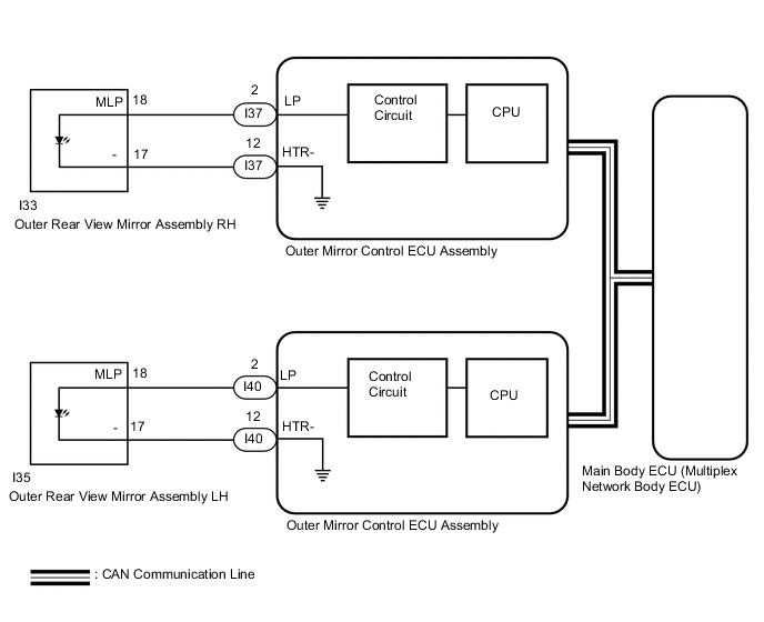
The outer mirror control ECU assembly controls the outer rear view mirror assembly (footwell) lights.
WIRING DIAGRAM
CAUTION / NOTICE / HINT
Note
-
If the main body ECU (multiplex network body ECU) is replaced, refer to Service Bulletin.
-
The lighting system uses CAN communication. First perform the inspections in "How to Proceed with Troubleshooting" to confirm that there are no communication malfunctions before proceeding with troubleshooting.
PROCEDURE
-
PERFORM ACTIVE TEST USING GTS (FR FOOT LIGHT)
-
Connect the GTS to the DLC3.
-
Turn the engine switch on (IG).
-
Turn the GTS on.
-
Enter the following menus: Body Electrical / Mirror / Active Test.
-
Perform the Active Test according to the display on the GTS.
Mirror Tester Display Measurement Item/Range Normal Condition Diagnostic Note Fr Foot Light Turns on the outer mirror foot lights/
ON or OFF
ON: Footwell light comes on
OFF: Footwell light off
- OK Outer rear view mirror assembly (footwell light) comes on.
OK 
PROCEED TO NEXT SUSPECTED AREA SHOWN IN PROBLEM SYMPTOMS TABLE (OUTER MIRROR CONTROL ECU ASSEMBLY WAS DEFECTIVE)
NG 
-
-
INSPECT OUTER REAR VIEW MIRROR ASSEMBLY
-
Remove the outer rear view mirror assembly Click here.
-
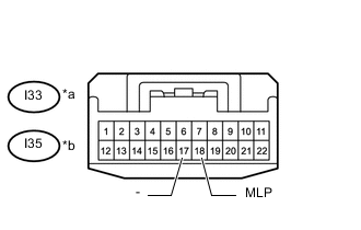
Text in Illustration *a Component without harness connected
(Outer Rear View Mirror Assembly RH)
*b Component without harness connected
(Outer Rear View Mirror Assembly LH)
Connect a positive (+) lead from the battery to terminal 18 (LP) and a negative (-) lead to terminal 17 (-).
-
Check that each function of the outer mirror footwell light operates normally.
OK Outer mirror footwell light illuminate. Result Result Proceed to OK A NG (RH Side) B NG (LH Side) C
B
REPLACE OUTER REAR VIEW MIRROR ASSEMBLY RH Click here
C
REPLACE OUTER REAR VIEW MIRROR ASSEMBLY LH Click here
A
-
-
CHECK HARNESS AND CONNECTOR (OUTER REAR VIEW MIRROR ASSEMBLY - OUTER MIRROR CONTROL ECU ASSEMBLY)
-
Disconnect the outer mirror control ECU assembly I37 and I40 connector.
-
Disconnect the outer rear view mirror Assembly I33 and I35 connector.
-
Measure the resistance according to the value(s) in the table below.
Standard Resistance Tester Connection Switch Condition Specified Condition I35-18 (MLP) - I40-2 (LP) Always Below 1 Ω I35-17 (-) - I40-12 (HTR-) Always Below 1 Ω I35-18 (MLP) or I40-2 (LP) - Body ground Always 10 kΩ or higher I33-18 (MLP) - I37-2 (LP) Always Below 1 Ω I33-17 (-) - I37-12 (HTR-) Always Below 1 Ω I33-18 (MLP) or I37-2 (LP) - Body ground Always 10 kΩ or higher
NG
REPAIR OR REPLACE HARNESS OR CONNECTOR
OK
-
-
CHECK OUTER MIRROR CONTROL ECU ASSEMBLY
-
Replace the outer mirror control ECU assembly with a new or known good one Click here.
-
Check that each function of the outer mirror footwell light operates normally.
OK Outer mirror footwell light illuminate. Result Result Proceed to OK A NG (for LHD) B NG (for RHD) C
A
END (OUTER MIRROR CONTROL ECU ASSEMBLY WAS DEFECTIVE)
B
REPLACE MAIN BODY ECU (MULTIPLEX NETWORK BODY ECU) Click here
C
REPLACE MAIN BODY ECU (MULTIPLEX NETWORK BODY ECU) Click here
-