LIGHTING SYSTEM Door Unlock Detection Switch Circuit
DESCRIPTION
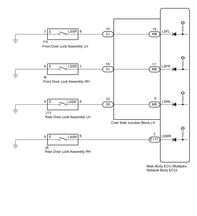
The main body ECU (multiplex network body ECU) detects the condition of each door unlock detection switch.
WIRING DIAGRAM
CAUTION / NOTICE / HINT
Note
-
If the main body ECU (multiplex network body ECU) is replaced, refer to Service Bulletin.
-
As the door control battery is installed between the vehicle battery and main body ECU (multiplex network body ECU), first perform the inspections in On-vehicle Inspection to confirm that there are no malfunctions in the power source circuit for the main body ECU (multiplex network body ECU) before performing this troubleshooting procedure Click here.
PROCEDURE
-
READ VALUE USING GTS (DOOR LOCK POSITION SWITCH)
-
Connect the GTS to the DLC3.
-
Turn the engine switch on (IG).
-
Turn the GTS on.
-
Enter the following menus: Body Electrical / Main Body / Data List.
-
Read the Data List according to the display on the GTS.
Main Body Tester Display Measurement Item/Range Normal Condition Diagnostic Note FR Door Lock Pos Front door unlock detection switch RH signal/
LOCK or UNLOCK
LOCK: Front door RH locked
UNLOCK: Front door RH unlocked
- FL Door Lock Pos Front door unlock detection switch LH signal/
LOCK or UNLOCK
LOCK: Front door LH locked
UNLOCK: Front door LH unlocked
- RR-Door Lock Pos SW Rear door unlock detection switch RH signal/
ON or OFF
ON: Rear door RH unlocked
OFF: Rear door RH locked
- RL-Door Lock Pos SW Rear door unlock detection switch LH signal/
ON or OFF
ON: Rear door LH unlocked
OFF: Rear door LH locked
- OK The display is as specified in the normal condition column. Result Result Proceed to OK A NG (Front door unlock detection switch RH does not operate) B NG (Front door unlock detection switch LH does not operate) C NG (Rear door unlock detection switch RH does not operate) D NG (Rear door unlock detection switch LH does not operate) E
A 
PROCEED TO NEXT SUSPECTED AREA SHOWN IN PROBLEM SYMPTOMS TABLE Click here
C 
INSPECT FRONT DOOR LOCK ASSEMBLY LH Click here
D
INSPECT REAR DOOR LOCK ASSEMBLY RH Click here
E
INSPECT REAR DOOR LOCK ASSEMBLY LH Click here
B 
-
-
INSPECT FRONT DOOR LOCK ASSEMBLY RH
-
Remove the front door lock RH Click here.
-
Inspect the front door lock RH Click here.
NG
REPLACE FRONT DOOR LOCK ASSEMBLY RH Click here
OK
-
-
CHECK HARNESS AND CONNECTOR (COWL SIDE JUNCTION BLOCK LH - FRONT DOOR LOCK RH AND BODY GROUND)
-
Disconnect the I6 front door lock RH connector.
-
Disconnect the 2J cowl side junction block LH connectors.
-
Measure the resistance according to the value(s) in the table below.
Standard Resistance Tester Connection Condition Specified Condition I6-7 (LSSR) - 2J-16 Always Below 1 Ω I6-8 (E) - Body ground Always Below 1 Ω I6-7 (LSSR) or 2J-16 - Body ground Always 10 kΩ or higher
NG
REPAIR OR REPLACE HARNESS OR CONNECTOR
OK
-
-
CHECK COWL SIDE JUNCTION BLOCK LH
-
Remove the cowl side junction block LH.
-
for LHD Click here.
-
for RHD Click here.
-
-
Remove the main body ECU (multiplex network body ECU) from the cowl side junction block LH.
-
for LHD Click here.
-
for RHD Click here.
-
-
Measure the resistance according to the value(s) in the table below.
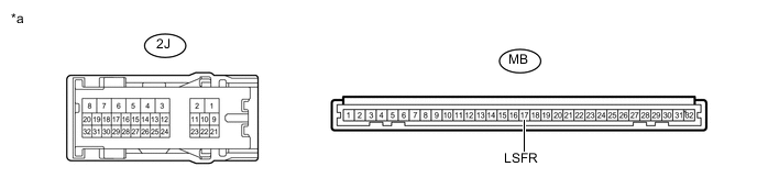
Text in Illustration *a Component without harness connected
(Cowl Side Junction Block LH)
- - Standard Resistance Tester Connection Condition Specified Condition MB-17 (LSFR) - 2J-16 Always Below 1 Ω MB-17 (LSFR) or 2J-16 - Body ground Always 10 kΩ or higher Result Result Proceed to OK (for LHD) A OK (for RHD) B NG (for LHD) C NG (for RHD) D
A
REPLACE MAIN BODY ECU (MULTIPLEX NETWORK BODY ECU) Click here
B
REPLACE MAIN BODY ECU (MULTIPLEX NETWORK BODY ECU) Click here
C
REPLACE COWL SIDE JUNCTION BLOCK LH Click here
D
REPLACE COWL SIDE JUNCTION BLOCK LH Click here
-
-
INSPECT FRONT DOOR LOCK ASSEMBLY LH
-
Remove the front door lock LH Click here.
-
Inspect the front door lock LH Click here.
NG
REPLACE FRONT DOOR LOCK ASSEMBLY LH Click here
OK
-
-
CHECK HARNESS AND CONNECTOR (COWL SIDE JUNCTION BLOCK LH - FRONT DOOR LOCK LH AND BODY GROUND)
-
Disconnect the I14 front door lock LH connector.
-
Disconnect the 2J cowl side junction block LH connectors.
-
Measure the resistance according to the value(s) in the table below.
Standard Resistance Tester Connection Condition Specified Condition I14-8 (LSSR) - 2J-19 Always Below 1 Ω I14-7 (E) - Body ground Always Below 1 Ω I14-8 (LSSR) or 2J-19 - Body ground Always 10 kΩ or higher
NG
REPAIR OR REPLACE HARNESS OR CONNECTOR
OK
-
-
CHECK COWL SIDE JUNCTION BLOCK LH
-
Remove the cowl side junction block LH.
-
for LHD Click here.
-
for RHD Click here.
-
-
Remove the main body ECU (multiplex network body ECU) from the cowl side junction block LH.
-
for LHD Click here.
-
for RHD Click here.
-
-
Measure the resistance according to the value(s) in the table below.

Text in Illustration *a Component without harness connected
(Cowl Side Junction Block LH)
- - Standard Resistance Tester Connection Condition Specified Condition MB-19 (LSFL) - 2J-19 Always Below 1 Ω MB-19 (LSFL) or 2J-19 - Body ground Always 10 kΩ or higher Result Result Proceed to OK (for LHD) A OK (for RHD) B NG (for LHD) C NG (for RHD) D
A
REPLACE MAIN BODY ECU (MULTIPLEX NETWORK BODY ECU) Click here
B
REPLACE MAIN BODY ECU (MULTIPLEX NETWORK BODY ECU) Click here
C
REPLACE COWL SIDE JUNCTION BLOCK LH Click here
D
REPLACE COWL SIDE JUNCTION BLOCK LH Click here
-
-
INSPECT REAR DOOR LOCK ASSEMBLY RH
-
Remove the rear door lock RH Click here.
-
Inspect the rear door lock RH Click here.
NG
REPLACE REAR DOOR LOCK ASSEMBLY RH Click here
OK
-
-
CHECK HARNESS AND CONNECTOR (MAIN BODY ECU (MULTIPLEX NETWORK BODY ECU) - REAR DOOR LOCK RH AND BODY GROUND)
-
Disconnect the J6 rear door lock LH connector.
-
Disconnect the E117 main body ECU (multiplex network body ECU) connectors.
-
Measure the resistance according to the value(s) in the table below.
Standard Resistance Tester Connection Condition Specified Condition J6-6 (LSSR) - E117-2 (LSWR) Always Below 1 Ω J6-9 (E) - Body ground Always Below 1 Ω J6-6 (LSSR) or E117-2 (LSWR) - Body ground Always 10 kΩ or higher Result Result Proceed to OK (for LHD) A OK (for RHD) B NG C
A
REPLACE MAIN BODY ECU (MULTIPLEX NETWORK BODY ECU) Click here
B
REPLACE MAIN BODY ECU (MULTIPLEX NETWORK BODY ECU) Click here
C
REPAIR OR REPLACE HARNESS OR CONNECTOR
-
-
INSPECT REAR DOOR LOCK ASSEMBLY LH
-
Remove the rear door lock LH Click here.
-
Inspect the rear door lock LH Click here.
NG
REPLACE REAR DOOR LOCK ASSEMBLY LH Click here
OK
-
-
CHECK HARNESS AND CONNECTOR (REAR DOOR LOCK LH - COWL SIDE JUNCTION BLOCK LH AND BODY GROUND)
-
Disconnect the J13 rear door lock LH connector.
-
Disconnect the 2K cowl side junction block LH connectors.
-
Measure the resistance according to the value(s) in the table below.
Standard Resistance Tester Connection Condition Specified Condition J13-6 (LSSR) - 2K-33 Always Below 1 Ω J13-9 (E) - Body ground Always Below 1 Ω J13-6 (LSSR) - 2K-33 or Body ground Always 10 kΩ or higher
NG
REPAIR OR REPLACE HARNESS OR CONNECTOR
OK
-
-
CHECK COWL SIDE JUNCTION BLOCK LH
-
Remove the cowl side junction block LH.
-
for LHD Click here.
-
for RHD Click here.
-
-
Remove the main body ECU (multiplex network body ECU) from the cowl side junction block LH.
-
for LHD Click here.
-
for RHD Click here.
-
-
Measure the resistance according to the value(s) in the table below.
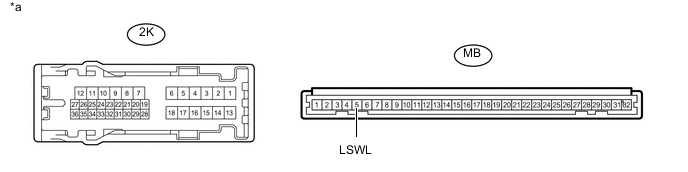
Text in Illustration *a Component without harness connected
(Cowl Side Junction Block LH)
- - Standard Resistance Tester Connection Condition Specified Condition MB-5 (LSWL) - 2K-33 Always Below 1 Ω MB-5 (LSWL) or 2K-33 - Body ground Always 10 kΩ or higher Result Result Proceed to OK (for LHD) A OK (for RHD) B NG (for LHD) C NG (for RHD) D
A
REPLACE MAIN BODY ECU (MULTIPLEX NETWORK BODY ECU) Click here
B
REPLACE MAIN BODY ECU (MULTIPLEX NETWORK BODY ECU) Click here
C
REPLACE COWL SIDE JUNCTION BLOCK LH Click here
D
REPLACE COWL SIDE JUNCTION BLOCK LH Click here
-